
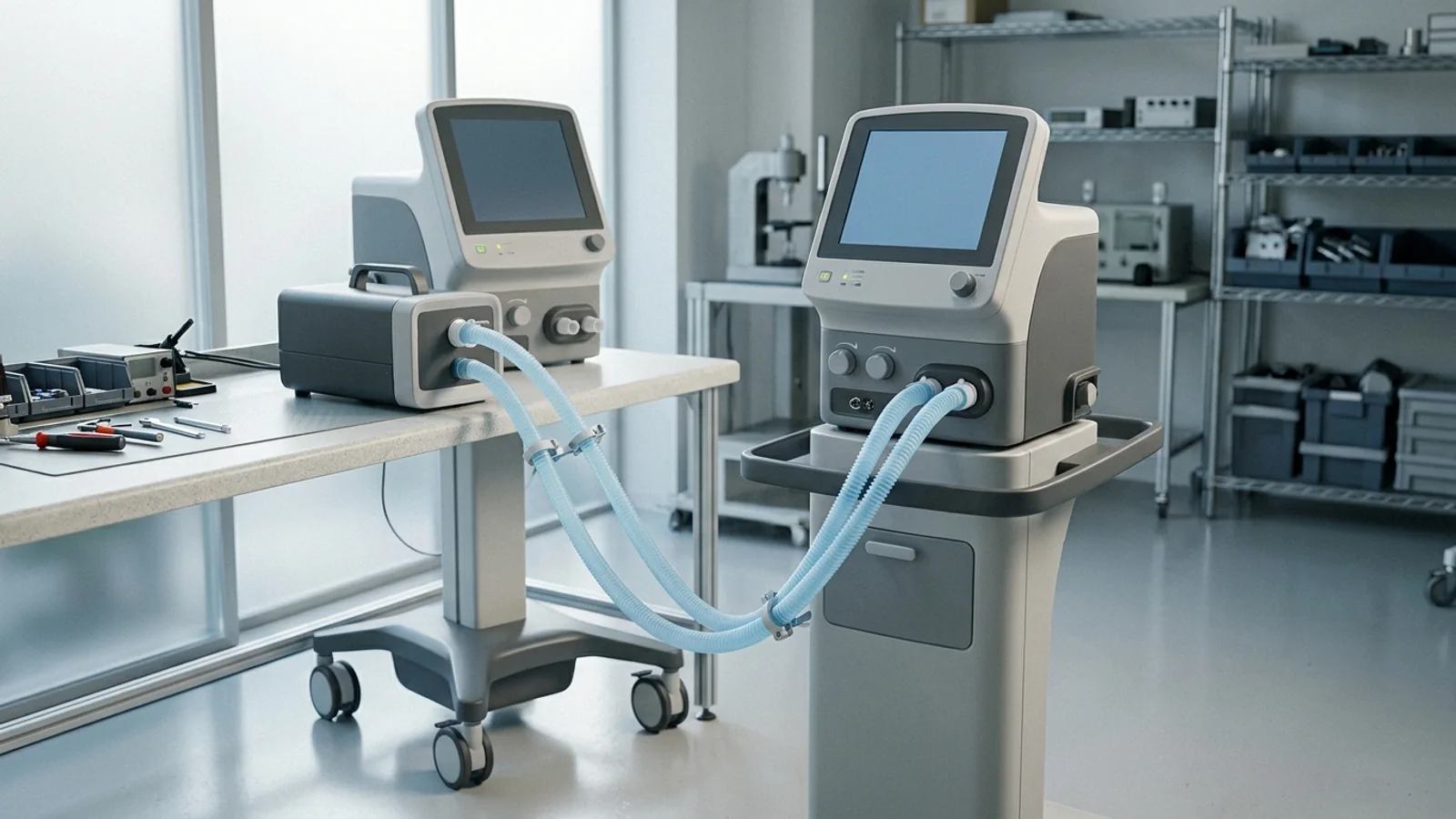
After a Major Repair, Performance Testing Is Not an Infusion-Pump Template
When a critical-care ventilator undergoes a corrective overhaul—such as replacing an inspiratory proportional valve, rebuilding an exhalation manifold, replacing internal oxygen blending solenoids, or loading firmware updates—the device cannot simply be powered on, run through an automated self-test, and rolled back into the intensive care unit. For biomedical equipment technicians (BMETs) and clinical engineering teams, returning a life-support mechanical ventilator to service presents a fundamentally different technical and regulatory challenge than servicing general floor equipment. Attempting to adapt an infusion pump return-to-service verification workflow or relying solely on an electrical safety testing after repair sequence leaves life-critical ventilation delivery completely unverified.
The hospital inspect-and-test-after-major-repair expectation originates in CMS hospital equipment-maintenance guidance. In Survey & Certification Letter S&C 14-07-Hospital (December 20, 2013), the Centers for Medicare & Medicaid Services (CMS) named ventilators as examples of hospital medical equipment and stated that all equipment “must be inspected and tested for performance and safety before initial use and after major repairs or upgrades.” In updated interpretive guidance in QSO-25-24-Hospitals (September 5, 2025) revising State Operations Manual (SOM) Appendix A under Tag A-0724 (governing 42 CFR 482.41(d)(2)), CMS restates this principle, noting that equipment “should be inspected and tested for performance and safety before initial use and after major repairs or upgrades,” while retaining A-0724’s statement that all equipment “must be inspected, tested, and maintained to ensure its safety, availability, and reliability.”
Clinical engineering leaders must keep the two CMS sentences distinct. QSO-25-24 uses “should” for inspect-and-test before initial use and after major repairs or upgrades, while the CoP at 42 CFR 482.41(d)(2) requires facilities, supplies, and equipment to be maintained to an acceptable level of safety and quality, and A-0724 still says all equipment must be inspected, tested, and maintained to ensure safety, availability, and reliability. Neither S&C 14-07 nor QSO-25-24 defines “major repair” by a universal numeric threshold or by a ventilator parts list. Whether the device remains on manufacturer-recommended maintenance or an already-documented AEM versus manufacturer-maintenance strategy is a prior program decision. For a life-support ventilator, the after-major-repair gate is an essential-performance question against the OEM specification, not an electrical-safety-standard-selection question and not a copy of an infusion-pump checklist.
Confirm the Device Is in ISO 80601-2-12 Critical-Care Scope
Before establishing a post-service verification plan, the service organization must confirm the governing standards boundary. The international particular standard governing critical-care mechanical ventilators is ISO 80601-2-12 Third edition 2023-11 (Medical electrical equipment — Part 2-12: Particular requirements for basic safety and essential performance of critical care ventilators). ISO 80601-2-12 establishes requirements for a critical-care ventilator in combination with its breathing system accessories. However, the standard's public scope is not a universal umbrella for all mechanical breathing devices; rather, it sets strict operational inclusion criteria and explicit exclusions.
To fall within the scope of ISO 80601-2-12, a device must satisfy three specific operational criteria:
Life-Sustaining Professional Equipment: The equipment is intended for use in a professional critical-care environment (such as an intensive care unit, step-down critical care unit, or specialized respiratory care area).
Professional Operator: The device is intended to be operated by a trained healthcare professional (such as a critical-care physician, respiratory therapist, or specialized intensive-care nurse).
Ventilator-Dependent Patient Population: The device is intended for patients who require differing levels of artificial ventilation support, explicitly including ventilator-dependent patients whose survival depends upon continuous mechanical gas exchange.
The standard clarifies that a critical-care ventilator may be transit-operable inside a professional healthcare facility. Intra-facility transport—such as moving an intubated patient from the ICU to radiology—remains fully within ISO 80601-2-12 scope and must not be confused with emergency transport equipment operated in pre-hospital emergency medical services (EMS).
Equally vital for clinical engineering triage is ISO 80601-2-12's explicit exclusion list. The standard expressly states that it does not apply to:
Anesthetic ventilators and anesthesia workstations, which are governed by ISO 80601-2-13;
Emergency medical service (EMS) transport ventilators, governed by ISO 80601-2-84;
Home healthcare ventilators intended for ventilator-dependent patients, governed by ISO 80601-2-72;
Home-care ventilatory support devices, governed by ISO 80601-2-79 and ISO 80601-2-80;
Obstructive sleep apnea therapy equipment, governed by ISO 80601-2-70;
Continuous positive airway pressure (CPAP) equipment;
Dedicated high-frequency jet or oscillatory ventilators, governed by ISO 80601-2-87;
Dedicated respiratory high-flow therapy devices, governed by ISO 80601-2-90; and
Constant-flow oxygen-therapy devices, cuirass ventilators, and iron lungs.
Furthermore, ISO 80601-2-12 contains an essential operational clarification: the standard does not apply to a ventilator operational mode solely intended for patients who are not dependent on artificial ventilation. When a critical-care ventilator operates in an auxiliary mode intended solely to augment spontaneous breathing for a non-dependent patient, that operational mode is not considered life-sustaining under the standard. While modern critical-care ventilators frequently feature integrated high-flow or non-invasive modes, their presence does not justify evaluating dedicated non-invasive or transport hardware under the critical-care standard.
From an FDA product-classification standpoint, continuous ventilators are classified under 21 CFR 868.5895. Within this regulation, the FDA assigns specific product codes that reflect the device's cleared indications. Product code CBK designates a “Ventilator, Continuous, Facility Use,” the facility-use continuous ventilator most readers will mean by critical-care ventilator. In contrast, product code MNS designates a continuous ventilator that is legally cleared as “Non-Life-Supporting,” and product code MNT is listed on the Rec# 1-187 sheet as “Sv70 Ventilator.” Technicians must confirm the model’s product code and cleared intended use: applying ISO 80601-2-12 life-sustaining criteria to an MNS device, or to any 868.5895 device whose labeling is not life-sustaining, without reviewing that labeling creates a false scope.
FDA Recognition Is a Premarket Edition Map, Not a Hospital Type-Test Script
On December 23, 2024, FDA entered the complete ISO 80601-2-12 Third edition 2023-11 on Recognition List 063 in its Recognized Consensus Standards database as Recognition Number 1-187, and incorporating it into the Accreditation Scheme for Conformity Assessment (ASCA). Concurrently, the FDA updated the status of ISO 80601-2-12 Second edition 2020-02 (Rec# 1-146), noting that declarations of conformity to the second edition will remain acceptable in premarket submissions until December 19, 2027. After that date, declarations of conformity to Rec# 1-146 will not be accepted.
While these dates are critical for medical device manufacturers seeking 510(k) clearance, clinical engineering professionals must understand what FDA recognition actually represents. As outlined in FDA's guidance document “Appropriate Use of Voluntary Consensus Standards in Premarket Submissions for Medical Devices,” recognized consensus standards provide a predictable pathway for manufacturers to demonstrate substantial equivalence during premarket review. FDA recognition of a revised standard edition is not an immediate hospital operational directive, nor does it mandate that healthcare technology management (HTM) departments retroactively rewrite their existing in-service preventive maintenance procedures or testing protocols.
Most importantly, FDA recognition does not grant service technicians license to invent numeric tolerances from memory or attempt to execute laboratory-type tests found in ISO 80601-2-12. The numeric pass/fail thresholds for an in-service ventilator derive strictly from the manufacturer's validated service documentation and IFU for that specific model, configuration, and software release. The standard defines what constitutes essential performance in design; the OEM IFU translates that definition into executable field-service test procedures.
What to Verify: Public Function Families and OEM Acceptance Criteria
Under 21 CFR 868.5895, the regulatory identification of a continuous ventilator establishes its public clinical functions: a Class II device intended to mechanically control or assist patient breathing by delivering a predetermined percentage of oxygen in the breathing gas. These two identification functions—control or assist of breathing, and delivery of a predetermined oxygen percentage—are the public function families to verify after corrective servicing. They are not a numeric tidal-volume, pressure, or FiO2 tolerance table.
To determine which performance characteristics to verify and where the criteria reside, use FDA’s May 10, 2024 remanufacturing guidance “Remanufacturing of Medical Devices: Guidance for Industry, Entities That Perform Servicing or Remanufacturing, and FDA Staff.” This article does not retell the published servicing-versus-remanufacturing decision tree. FDA recommends that OEM labeling of reusable devices include, as applicable:
Key performance and safety specifications, and device-specific performance specifications with examples that include flow-rate accuracy or range;
Recommended maintenance schedules, inspection procedures, and routine servicing activities;
Recommended troubleshooting procedures, routine testing methodologies, and explicit acceptance criteria to confirm the device remains within its original performance and safety specifications;
A description of error codes, alerts, and alarm features on the device; and
Version number and release date of software needed to return the device to OEM specifications.
Commercial test-equipment manufacturers publish application guides that outline typical ventilator test menus. TSI’s public explainer, for example, lists leak checking, high- and low-pressure accuracy, volume delivery, air and oxygen flow accuracy, and alarm checks, and states that different ventilator models use different procedures. Those families are public vendor context for what a gas-flow analyzer can measure; they are not a CMS or ISO checklist and they are not a substitute for the OEM IFU.
Vendor articles are educational context for instrument setup, not regulatory standards. Do not adopt a generic numeric tolerance across models. Pass/fail determinations must reference the exact acceptance criteria published in the manufacturer's service documentation for that model, configuration, and software version.
Alarms, Gas Monitoring, and Humidification as Companion Functions
A critical-care ventilator functions as an integrated life-support ecosystem. In addition to delivering mechanical breaths, the system relies on collateral alarm systems, integrated physiological gas monitoring, and auxiliary breathing-circuit conditioning. Each of these functions is governed by companion consensus standards recognized by the FDA and must be systematically verified during post-repair testing.
Alarm System Verification (IEC 60601-1-8)
Alarm systems in critical-care ventilators are governed by IEC 60601-1-8 Edition 2.2 2020-07 (recognized by FDA as Rec# 5-131, and nationally adopted as ANSI/AAMI/IEC 60601-1-8:2006 and A1:2012 including AMD 2:2021). As a collateral standard in the 60601 series, IEC 60601-1-8 establishes requirements for alarm signals, visual indicators, and alarm presets. Post-service verification must confirm:
OEM-required alarm conditions: Confirm the alarm, alert, and error features the service IFU requires for the ventilation modes that will be used clinically, including how those conditions are announced.
Priority and signaling behavior: IEC 60601-1-8 is the collateral alarm-system standard; verify that the required visual and auditory signals still operate as the OEM routine specifies. Do not invent sound-pressure, delay, or priority numeric limits from the paywalled collateral text.
No improvised trigger method: Do not write or perform live high-pressure occlusion or circuit-disconnection maneuvers as a generic shop method. Use the OEM’s specified test setup, typically a benchtop test lung and the checks the IFU names.
Power-loss features if the IFU requires them: If the OEM routine includes backup-power or mains-failure checks, perform those checks as written in the IFU rather than improvising an unplug procedure.
Technicians must not attempt to invent delay times or sound-pressure levels from paywalled standard clauses; instead, they must verify the specific alarm conditions and trip points specified in the OEM service routine.
Integrated Respiratory Gas Monitoring (ISO 80601-2-55)
When a critical-care ventilator incorporates an integrated or modular respiratory gas monitor (RGM) for end-tidal CO2 (EtCO2) or fractional inspired oxygen (FiO2), the companion standard is ISO 80601-2-55:2018 including AMD1:2023 (FDA Rec# 1-184, recognized December 23, 2024; premarket declarations of conformity to the prior Rec# 1-140 remain valid until December 20, 2026). ISO 80601-2-55 explicitly notes that an RGM may be stand-alone or integrated directly into a ventilator. When present, verify the oxygen and carbon-dioxide monitoring functions the OEM IFU names for that configuration. Do not invent FiO2 or ETCO2 accuracy windows, and do not assume a particular sensor chemistry or optical-bench method unless the IFU names it.
Breathing System Humidification (ISO 80601-2-74)
ISO 80601-2-12's scope explicitly covers accessories connected to the breathing system where those accessories can affect basic safety or essential performance. ISO 80601-2-74:2021 (FDA Rec# 1-177) specifies requirements for respiratory humidifiers and provides an explicit example: when a heated humidifier or heated breathing-tube controller is incorporated into a critical-care ventilator, ISO 80601-2-12 applies concurrently. While ISO published a 2026 revision of ISO 80601-2-74, the FDA's recognized edition as of the December 2024 consensus list remains the 2021 second edition. When the serviced configuration includes an active humidifier or heated breathing-tube controller, treat humidification as a companion function and verify it per the OEM IFU. Do not invent humidity numeric limits or a universal heater-wire protocol.
Electrical Safety Is Required and Not Sufficient
A frequent misconception in clinical engineering is that completing an automated electrical safety test (EST) provides sufficient evidence to return a repaired medical device to patient care. In reality, electrical safety testing represents a necessary baseline of physical safety, but it provides zero evidence regarding essential performance.
The international standard governing in-service electrical safety is IEC 62353:2014 (Medical electrical equipment — Recurrent test and test after repair of medical electrical equipment). The public scope of IEC 62353 explicitly defines its boundaries:
Testing After Repair: IEC 62353 applies to recurrent testing and testing after repair of medical electrical equipment to assess electrical safety. It is not a substitute for essential-performance verification.
Not a Design Conformity Assessment: The standard expressly states that it is not suitable to evaluate whether medical electrical equipment or systems comply with the relevant design standards (such as ISO 80601-2-12 or IEC 60601-1).
No Repair Requirements: IEC 62353 does not define requirements for repair, component replacement, or device modification.
An electrical safety analyzer can confirm the hospital’s chosen after-repair electrical-safety method passed. It cannot show that delivered volume, pressure, or oxygen percentage still meet the OEM specification. For a life-support ventilator, electrical safety testing is a parallel requirement under the hospital’s in-service electrical-safety procedure and 42 CFR 482.41(d)(2), never a substitute for ventilation-delivery verification. For choosing among in-service electrical-safety methods, use the published analysis of electrical safety testing after repair.
Life-Support ITM Evidence on the Work Order
For life-support equipment, inspection, testing, and maintenance that is not in the record cannot be shown as complete. The work order is the evidence object surveyors can read.
In The Joint Commission's 2025 Hospital Life Safety & Environment of Care Document List and Review Tool, EC.02.04.03 EP 2 Note 1 treats life-support equipment as high-risk medical equipment. Note 2 states that required inspect, test, and maintain activities and associated frequencies must have a 100% completion rate. Accreditation 360 relocated Environment of Care medical-equipment standards beginning January 2026; this article does not invent successor Physical Environment element-of-performance numbers. Use the 2025 review tool as public evidence that life-support inspect/test/maintain work is documented and that required activities and frequencies must be 100% complete. CMS Tag A-0724 remains the durable Conditions of Participation hook.
To make the work order survey-readable under CMS Tag A-0724 and Joint Commission high-risk ITM documentation, record:
Unique Device Identification: Hospital asset tag, manufacturer name, equipment model, chassis serial number, and clinical department location (aligning with CMMS medical equipment inventory unique identification standards);
Software and Firmware Release: The exact installed operational firmware and user-interface software versions, confirming that post-service code versions match validated manufacturer revisions;
Service Description & Servicing Boundary: Detailed description of corrective work performed, parts replaced (with lot and serial numbers), and affirmative evidence confirming the work constitutes routine servicing rather than remanufacturing (referencing our guide on medical device servicing vs remanufacturing);
Test Instrument Traceability: Model, serial number, and current calibration expiration date for all test equipment utilized, including the biomedical gas-flow analyzer, digital pressure manometer, and electrical safety analyzer;
Quantitative Verification Results: Numerical test data recorded at the setpoints the OEM IFU names, showing measured values alongside the OEM’s published acceptance criteria for those tests—not a generic volume, PEEP, or FiO2 cookbook;
Alarm System Sign-Off: Itemized verification of the alarm, alert, and error features the OEM IFU requires for the modes that will be used clinically; and
Return-to-Service Authorization: Formal release sign-off by a qualified biomedical technician, including technician identifier, completion timestamp, and supervisor approval, fulfilling medical equipment service record requirements.
A Scope-and-Evidence Matrix, Not a Numeric Cookbook
To establish an audit-ready, manufacturer-neutral operational standard, clinical engineering programs should implement a structured decision matrix that links standards scope, regulatory triggers, verification layers, and work order documentation. The matrix below synthesizes the necessary verification gates:
| Verification Layer | Regulatory or Standards Hook | Scope & Criteria Source | Required Work Order Evidence |
|---|---|---|---|
| 1. Device Scope & Classification | 21 CFR 868.5895; FDA Product Code CBK | ISO 80601-2-12:2023 public scope; OEM technical manual | Confirmed critical-care continuous ventilator scope; asset tag, serial number, and firmware version. |
| 2. Regulatory Trigger | CMS SOM Appendix A Tag A-0724; 42 CFR 482.41(d)(2); S&C 14-07 | Inspect and test for performance and safety after major repairs | Nature of corrective repair documented; confirmation of servicing boundary versus remanufacturing. |
| 3. Ventilation Delivery | 21 CFR 868.5895 (mechanical control/assist of breathing) | OEM IFU and service manual specifications (flow, volume, pressure) | Quantitative flow, pressure, and tidal volume measurements recorded using calibrated analyzer against OEM limits. |
| 4. Gas Blending & Concentration | 21 CFR 868.5895 (predetermined oxygen percentage delivery) | OEM IFU acceptance criteria; ISO 80601-2-55 if RGM integrated | Oxygen-percentage delivery verified at the setpoints the OEM IFU names, against OEM acceptance criteria. |
| 5. Alarm System Integrity | IEC 60601-1-8 (FDA Rec# 5-131); ISO 80601-2-12 | OEM IFU alarm verification protocols (auditory, visual, priority tiers) | OEM-required alarm/alert/error features for the clinically used modes documented as checked. |
| 6. Auxiliary Accessories | ISO 80601-2-74 (heated humidification); ISO 80601-2-12 | OEM IFU companion accessory test procedures | Humidifier circuit continuity, temperature sensor communication, and alarm handshakes recorded. |
| 7. Electrical Safety Baseline | 42 CFR 482.41(d)(2); NFPA 99 / IEC 62353 | Hospital established in-service electrical safety test procedure | Protective earth resistance and chassis leakage current values recorded with numerical pass determination. |
| 8. Return-to-Service Authorization | Joint Commission EC.02.04.03 (100% completion); CMS Tag A-0724 | Hospital Medical Equipment Management Plan (MEMP) | Complete quantitative test package, technician credentials, authorization timestamp, and CMMS record closure. |
The following decision flow illustrates the sequential gate process that clinical engineering teams must execute before releasing a repaired critical-care ventilator back to the intensive care unit:
graph TD
  A["Intake Repaired Ventilator"] --> B{"Scope Check: ISO 80601-2-12"}
  B -->|"Exclusion: EMS / Anesthesia / Home"| C["Route to Dedicated Particular Standard & IFU"]
  B -->|"In Scope: Life-Sustaining Facility Use (CBK)"| D["Log Work Order: Model, Serial, Firmware"]
  D --> E["Electrical Safety Testing (IEC 62353 / NFPA 99)"]
  E --> F{"EST Passed?"}
  F -->|No| G["Isolate Electrical Fault & Repair"]
  F -->|Yes| H["Connect Calibrated Gas Flow Analyzer & Test Lung"]
  H --> I["Verify Breathing Delivery (Pressure, Volume, Flow per OEM IFU)"]
  I --> J["Verify Gas Concentration (O2 Blending per OEM IFU)"]
  J --> K["Verify Alarm Signaling (IEC 60601-1-8 per OEM IFU)"]
  K --> L["Verify Integrated Accessories (RGM / Humidifier if fitted)"]
  L --> M{"All Results Within OEM Acceptance Criteria?"}
  M -->|No| N["Recalibrate or Troubleshoot Pneumatics"]
  M -->|Yes| O["Record Quantitative Data & Instrument Traceability in CMMS"]
  O --> P["Record required ITM completion and authorize return to service"]
P --> Q["Release Ventilator to Intensive Care Unit"]Treat ventilator essential-performance verification as a structured evidence process: ISO 80601-2-12’s public scope names the device class and exclusions, CMS names the after-major-repair inspect-and-test trigger, and the OEM IFU names the limits. That is the manufacturer-neutral plan a work order can actually defend.