
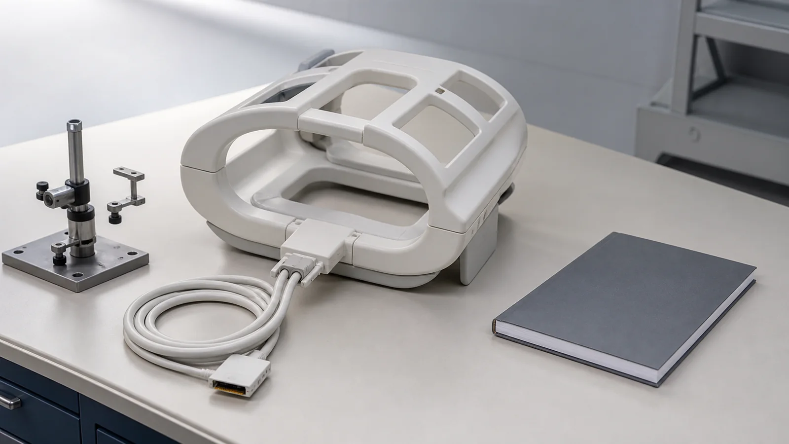
In diagnostic magnetic resonance imaging (MRI), radiofrequency (RF) receiver coils represent both the most critical link in the signal acquisition chain and one of the highest ongoing maintenance expenditures for clinical engineering departments. High-density 32-channel or 64-channel phased-array neurovascular, cardiac, or orthopedic coils are among the most expensive RF accessories in the MRI suite. OEM replacement and exchange prices vary widely by model and should be confirmed from current quotes rather than assumed list prices. When an imaging technologist reports image banding, localized signal loss, or intermittent artifact during high-gradient sequences, clinical engineering and radiology leaders must make a rapid, evidence-grounded decision: should the coil be sent for independent component-level bench repair, traded in via an OEM exchange program, or retired and replaced entirely?
This decision cannot be made based on purchase price or vendor turnaround promises alone. An improper repair can degrade signal-to-noise ratio (SNR), introduce channel phase cancellation, or—most critically—cause catastrophic RF burns from compromised patient dielectric insulation or failed passive/active blocking networks. This framework provides an objective, four-tier failure classification system, RF engineering decision logic, and verification protocols that use measurement methods from NEMA MS series standards, AAPM Report 100, and IEC 60601-2-33.
The Economics and Operational Risks of MRI Coil Degradation
Modern MRI receiver coils are subjected to intense mechanical stress, repetitive flexing, chemical exposure from hospital-grade disinfectants, and intense electromagnetic gradients. Mechanical wear and cable-harness fatigue are frequent drivers of coil-related service, but the cited NEMA, AAPM, ACR, and IEC documents do not assign a universal percentage of events to any failure mode.
When evaluating whether to repair or replace, healthcare technology management (HTM) leaders face three distinct operational risk vectors:
Scanner Downtime vs. Loaner Logistics: Taking an essential coil out of rotation without a verified loaner immediately impairs clinical workflow and patient scheduling. Facilities should use their own scanner-hour and delay costs; no cited standard establishes a universal MRI-hour value.
Subtle Multi-Channel Dropout: In 16-, 32-, or 64-channel phased arrays, a single failed element or degraded preamplifier often goes unnoticed during routine clinical scans because neighboring elements compensate through parallel imaging algorithms (SENSE, GRAPPA). However, the localized SNR drop degrades deep-tissue resolution and increases reconstruction artifacts.
Patient Thermal Safety Hazards: During transmit RF pulses, receiver coil loops must be reliably decoupled (detuned) via PIN diode bias circuits. If a PIN diode fails short or open, or if cable balun traps overheat, intense RF currents can induce severe thermal burns on patient skin.
Four-Tier Failure Classification: Repair vs. Replace Matrix
To standardize triage across clinical engineering teams, coil failure modes should be categorized into four distinct technical tiers. Each tier defines the underlying physical defect, diagnostic indicators, a qualitative economic note, and the appropriate service pathway. Dollar savings percentages are not published in the cited standards.
| Failure Tier | Physical Defect & Symptoms | Economic note | Recommended Action | Validation Requirement |
|---|---|---|---|---|
| Tier 1: External Mechanical & Cable Harness | Strain relief splitting, coaxial dielectric fatigue, broken connector pins, intermittent image snow on cable flex | Often lower than OEM exchange when validated; treat quoted savings as facility-specific, not a published benchmark | Component Repair / Re-cable | TDR impedance test, flex continuity, DC loop resistance |
| Tier 2: Discrete Active/Passive RF Circuitry | PIN diode short/open, blown low-noise preamp (LNA), cracked ceramic chip capacitor, detuning trap drift | May be economical if RF metrology is available; do not assume a standard savings percentage | Specialized Bench Repair | S-parameter network analysis, diode forward/reverse bias, bench SNR |
| Tier 3: Multi-Element Flexible Array Potting | High-density flexible array conductor trace fracture, potting delamination, internal fluid ingress into foam matrix | Rebuild cost can approach exchange; require a written feasibility and validation plan | Rebuild or Exchange Evaluation | NEMA MS-9 phased-array characterization versus site baseline; do not treat a single S21 number as a universal limit |
| Tier 4: Catastrophic Structural & Thermal Breach | Rigid housing structural fracture across patient interface, charred PCB from RF arcing, severe coil form distortion | Repair is generally not appropriate; plan OEM exchange or retirement | OEM Exchange or Retirement | Do not return to service on cosmetic repair; escalate under IEC 60601-2-33 RF/thermal safety and facility policy |
As detailed in the matrix above, Tiers 1 and 2 represent the sweet spot for third-party component overhaul. Independent service organizations (ISOs) equipped with RF micro-soldering stations, vector network analyzers, and automated cable test benches can replace individual surface-mount PIN diodes, discrete non-magnetic capacitors, and custom coaxial bundles with identical or superior tolerances. Conversely, Tier 4 breaches must never be patched with unvalidated surface epoxies or consumer adhesives, which alter dielectric constants and fail clinical flammability and biocompatibility standards.
Diagnostic Decision Workflow for Clinical Engineering
When a coil is pulled from clinical service, the biomedical equipment technician (BMET) or imaging specialist should execute the following systematic diagnostic workflow before initiating an external RMA or purchase order.
flowchart TD
    Start["Coil artifact or failure reported"] --> Step1["Visual and mechanical housing inspection"]
    Step1 --> DecisionHousing{"Housing cracked, charred, or fluid ingress?"}
    DecisionHousing -- "Yes (safety breach)" --> Tier4["Tier 4: reject repair — OEM exchange or retire"]
    DecisionHousing -- "No (housing intact)" --> Step2["Cable harness and interconnect test"]
    Step2 --> DecisionCable{"Cable continuity, connector, or strain-relief fault?"}
    DecisionCable -- "Yes" --> Tier1["Tier 1: cable harness rebuild and connector overhaul"]
    DecisionCable -- "No" --> Step3["Bench RF analysis: PIN bias and S-parameters"]
    Step3 --> DecisionRF{"Discrete component fault (diode / preamp / trap)?"}
    DecisionRF -- "Yes" --> Tier2["Tier 2: discrete RF component replacement and retuning"]
    DecisionRF -- "No" --> Step4["Element potting and multi-channel decoupling audit"]
    Step4 --> DecisionArray{"Internal flexible-array potting failure?"}
    DecisionArray -- "Yes" --> DecisionEcon{"Rebuild technically and economically feasible versus exchange?"}
    DecisionEcon -- "Feasible" --> Tier3["Tier 3: factory array rebuild and repotting"]
    DecisionEcon -- "Not feasible" --> Retire["Retire coil / procure replacement"]
    Tier1 --> Step5["Phantom QA: NEMA MS-1 SNR, MS-3 uniformity, MS-9 array methods"]
    Tier2 --> Step5
    Tier3 --> Step5
    Step5 --> DecisionQA{"Meets site baseline and physicist/ACR action levels?"}
    DecisionQA -- "Pass" --> RTS["Return to clinical service with a traceable record"]
DecisionQA -- "Fail" --> ReCalibrate["Retune / escalate to secondary bench audit"]Verifying Restored Performance: Standardized RF Bench and Phantom Protocols
A successful MRI coil repair is not complete upon reassembly; it is complete only when quantitative physical testing proves that electrical tuning, active decoupling, and image signal quality have been restored to baseline manufacturer specifications. Service organizations must execute a two-stage validation protocol combining bench-level RF metrology and scanner-level phantom imaging.
Stage 1: Bench-Level RF Characterization
Before a repaired coil is connected to a live MRI scanner, the bench technician must verify the following parameters using a calibrated Vector Network Analyzer (VNA) and dedicated DC bias power supply:
Resonance Frequency Tuning (S11 Return Loss): Each coil element is typically tuned near the system Larmor frequency (about 63.86 MHz at 1.5 T and 127.73 MHz at 3.0 T). Some RF laboratories use a loaded return-loss example target such as S11 better than −18 dB; that figure is a shop heuristic, not a NEMA MS-1 or IEC pass/fail limit. Record the coil-family baseline and any OEM specification actually in hand.
Active PIN Diode Decoupling Isolation: Forward and reverse PIN bias should demonstrate that the element detunes during transmit. Isolation differentials such as 25 dB to 30 dB are example bench targets used by some RF shops, not values published as acceptance limits in NEMA MS-1, MS-9, or IEC 60601-2-33. Compare with the coil's documented detuning method and baseline.
Inter-Element Decoupling (S12 / S21 Isolation): Adjacent phased-array elements are decoupled by geometric overlap, capacitive networks, or preamplifier decoupling. Isolation values such as −15 dB to −20 dB are hypothetical shop targets unless an OEM or site baseline specifies them. Characterize coupling with a calibrated VNA and retain the traces.
Preamplifier Gain and Noise Figure: Integrated low-noise preamplifiers should be consistent across channels relative to the coil's original design. Gain and noise-figure bands sometimes quoted in RF literature (for example 25 dB to 30 dB gain or noise figure below 0.8 dB) are not NEMA or ACR acceptance criteria. Use matched replacement parts and compare channel-to-channel behavior to baseline.
Stage 2: Scanner-Level Phantom QA (NEMA and ACR Protocols)
Once bench qualification is confirmed, the coil must undergo imaging tests on the clinical MRI scanner using standardized QA phantoms in accordance with recognized medical physics protocols:
Signal-to-Noise Ratio (SNR) per NEMA MS-1: NEMA MS-1 defines measurement methods (including two-image subtraction and single-acquisition background-noise approaches) for single-channel volume coils. It does not set a universal ±5% repair-acceptance band. Compare post-repair SNR in defined ROIs with commissioning baseline and with action levels set by the qualified medical physicist.
Percent Image Uniformity (PIU) per NEMA MS-3 / ACR QC: NEMA MS-3 defines how to measure image uniformity for single-channel volume coils. ACR MRI accreditation phantom tests publish field-strength-specific percent image uniformity criteria for volume-coil phantom images (commonly distinguished for <3 T versus 3 T, and for large versus medium phantoms). Those ACR figures apply to accreditation phantom geometry, not as a generic post-repair limit for every surface or flexible array. Follow current ACR QC materials and physicist-set action levels.
Phased Array Element Noise Correlation per NEMA MS-9: NEMA MS-9 defines methods for characterizing receive-only phased-array coils, including SNR and uniformity of the combined and individual channels. Off-diagonal noise-correlation coefficients below 0.2 to 0.3 are a hypothetical interpretation aid used by some sites, not a published MS-9 pass/fail table. A dead channel or failed preamplifier typically appears as missing variance or abnormal cross-channel correlation relative to that coil's own noise matrix.
The cited standards do not publish OEM list prices, typical ISO repair invoices, or a savings percentage by array type. Use the decision factors below with actual quotes and measured RF data. Any cost comparison that appears in a purchase request should be labeled as that transaction's numbers, not as a national benchmark.
| Decision factor | Why it matters | Evidence to record |
|---|---|---|
| Loaner or spare coil availability | Scanner downtime cost is facility-specific and is not published in NEMA, ACR, or IEC documents. | Loaner compatibility, expected turnaround, and whether clinical scheduling can absorb the outage. |
| Quoted repair versus OEM exchange | Third-party repair can be less expensive than OEM exchange, but no cited source supports a standard 50–70% savings band or a fixed OEM price ladder by channel count. | Written quotes, remaining warranty, and whether the repair includes the validation protocol the site requires. |
| Independent RF and phantom validation | A low price is not an acceptance criterion. NEMA MS-1/MS-3/MS-9 and ACR QC describe how to measure restored performance. | VNA traces, PIN-bias records, phantom SNR/uniformity versus baseline, and calibration status of test equipment. |
| Housing and detuning integrity | IEC 60601-2-33 frames RF heating and coil thermal safety as essential-performance issues, not optional cosmetic checks. | Housing-seal inspection, fluid-ingress findings, and evidence that active/passive detuning still functions. |
Safety Boundaries and Return-to-Service Documentation Checklist
Before a repaired coil is released back into the clinical scheduling pool, the healthcare facility must ensure that a complete, contemporaneous service record is archived in the Computerized Maintenance Management System (CMMS) in alignment with AAPM Report 100 and hospital accreditation requirements.
The service documentation package must verify and record the following seven mandatory data points:
Unique Asset Identification: Coil model, OEM serial number, scanner system compatibility ID, and facility CMMS asset control number.
Visual Housing & Cable Integrity Pass: Confirmation that outer shell seals, flex joints, strain reliefs, and connector pins exhibit zero cracks, discoloration, or fluid entry.
Replaced Components Log: Detailed listing of all replaced semiconductors (PIN diodes), RF capacitors, coaxial segments, and preamplifiers including component lot numbers and non-magnetic verification.
Quantitative Bench RF Metrology: Pre- and post-repair S11 return loss, active detuning attenuation (dB), and DC bias switching currents.
Standardized Phantom SNR & PIU Results: Comparison of post-repair phantom image metrics against baseline historical commissioning scans.
Test Equipment Traceability: Serial numbers and valid calibration expiration dates for all VNAs, oscilloscopes, RF power meters, and multimeters used.
Authorized Return-to-Service Sign-Off: Dated authorization by a qualified biomedical imaging specialist or certified clinical engineer.
Advanced Technical and Operational Service Considerations
Field Strength Variations (1.5T vs. 3.0T vs. 7.0T) and Tuning Tolerances
Higher magnetic field strengths operate at significantly higher Larmor frequencies (~63.86 MHz at 1.5 Tesla, ~127.73 MHz at 3.0 Tesla, and ~298 MHz at 7.0 Tesla), where dielectric sample loading effects and parasitic capacitances become pronounced. At 3.0 T and 7.0 T, inter-element coupling and patient body loading shift resonance and match more than at 1.5 T. Some laboratories therefore use tighter example bench targets (for instance loaded S11 better than −20 dB or detuning isolation greater than 30 dB). Those figures remain shop heuristics unless the OEM specification or site baseline states them. The safety concern—B1 distortion, shading, and local RF heating—is real; the numeric gates are not IEC or NEMA mandates.
Dielectric Insulation and Housing Integrity Under IEC 60601-2-33
Any through-wall crack, seam separation, or delamination along the patient-contacting surface of an RF receiver coil compromises the essential dielectric barrier mandated by IEC 60601-2-33. Even hairline cracks permit conductive patient perspiration, saline, or hospital-grade disinfectants to penetrate the interior potting and reach high-voltage tuning capacitors or balun traps. When fluid ingress occurs, capacitive coupling directly to patient skin can cause instantaneous RF arcing and severe contact burns. Under medical electrical safety standards, structural patching of cracked housings with uncertified epoxy or consumer adhesives is strictly unacceptable; the entire outer shell must be replaced or the coil exchanged via OEM pathways.
Multi-Channel Noise Correlation Matrix Analysis (NEMA MS-9)
In high-density phased arrays (e.g., 32-channel or 64-channel coils), parallel reconstruction algorithms (such as SENSE, GRAPPA, or ARC) synthesize missing image data from adjacent channels, making a single dead element difficult to detect on routine anatomical scans. By acquiring a noise-only raw k-space matrix (without RF transmit excitation) in accordance with NEMA MS-9 protocols, medical physicists compute the noise covariance between all receiver channels. A severed coaxial trace, blown preamplifier, or detuning-diode fault typically appears as missing variance or abnormal cross-channel correlation relative to that coil's own noise matrix. Treat a numeric cutoff such as off-diagonal coefficients above 0.3 as a hypothetical flag unless the site physicist has adopted it as an action level.
Total Cost of Ownership (TCO) and Lifecycle Replacement Triggers
The economic crossover point depends on remaining useful life as estimated by the facility, failure tier, loaner availability, and whether post-repair RF validation can actually be performed. Published sources cited here do not support a seven-to-ten-year retirement rule, a 40% six-month re-failure probability, or a 50% repair-to-exchange threshold. When quotes, cumulative failures, and missing validation capability make exchange the lower operational risk, choose exchange or replacement and record the rationale.