
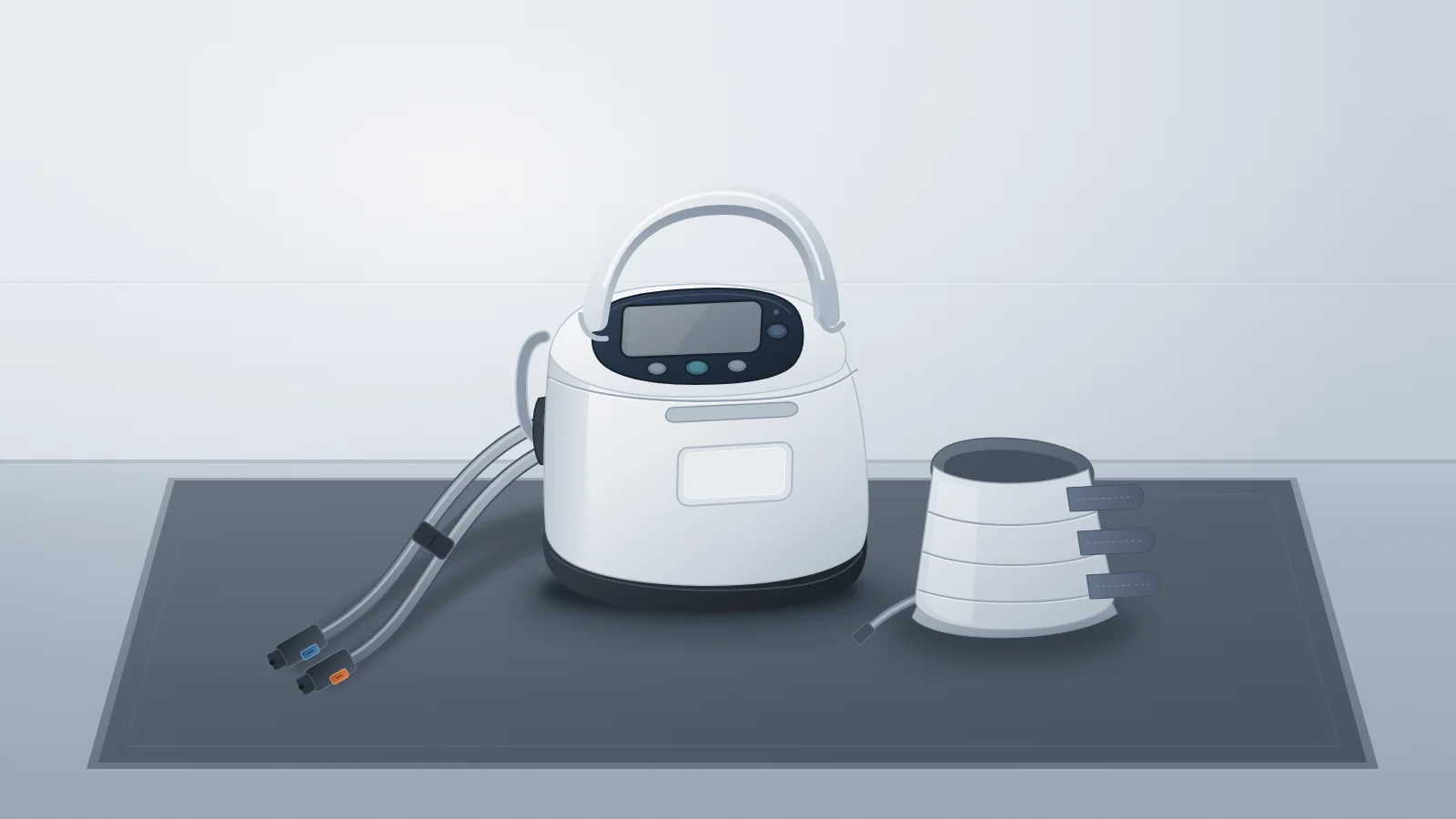
When a clinical unit reports that a Flowtron ACS900 alarm disappeared after someone pressed Standby, ask the reporter to record the exact LCD text and companion icons, the front and underside LED colors, the operating mode and power source at onset, and whether the alert involved tubeset connector 1 (blue), connector 2 (orange), or both. Under the U.S.-listed Flowtron ACS900 Instructions for Use (526933EN_16, November 2024), pressing the middle control button to place the pump in Standby clears active warning and alarm screens—so the display observation is lost at intake unless someone captures it before resetting or swapping garments.
That intake snapshot determines which of three distinct service routes the complaint belongs on: external garment or tubing follow-up (Low pressure/leak, Kinked/blocked tube, or Garment disconnected), a scheduled preventive-maintenance request (Service required with the spanner icon and green LEDs), or switching off the pump and calling the service engineer, as the IFU directs (Faulty Tubeset, Hardware fail with ERR and a two- or three-digit fault code, or CAL). Recording a cleared or unreproduced alarm as a display event keeps fault resolution and return-to-service evidence separate from initial intake.
Read the display before routing the call
Before assigning a Flowtron ACS900 ticket to supply follow-up, scheduled maintenance, or corrective repair, confirm the exact unit configuration and applicable documentation. On the Arjo U.S. Flowtron ACS900 product page, Arjo identifies Standard and Operating Room configurations and links the English IFU (526933EN_16, November 2024) alongside the Quick Reference Guide — Controls (526936EN_04, January 2021). IFU technical specifications (p. 30) list pump part numbers including 526000-XX and the America variant 526000-01/02-P, so recording the installed model and part number ensures the handoff matches the facility's market and revision.
Clinical staff often summarize an alert from memory using one label—"the wrench came on," "it showed ERR," or "it had a tubeset alarm." In the Quick Reference Guide, the spanner (wrench) symbol carries a combined legend label: Hardware fault detected or periodic service required. Only the full IFU troubleshooting tables (pp. 24–29) separate those conditions by companion indicators, LED color, and pump state:
Companion icons and text change the meaning of a symbol: a spanner at the right of the LCD with green LEDs indicates Service required (normally after the preset service interval expires, while therapy can continue until service is available); a permanent spanner with
ERRin the top left and a two- or three-digit fault code in the bottom right indicates Hardware fail with therapy suspended; and a flashing spanner paired with a flashing battery icon indicates a Battery fault.ERR appears in two different fault paths: beyond Hardware fail, the IFU notes that if internal pump temperature exceeds 60 °C, an
ERRscreen appears and stops therapy, instructing the user to switch off the pump, allow it to cool, and switch it back on—escalating to a service engineer only if the alarm continues. Recording whether a High Temperature warning icon preceded the screen or whether a two- or three-digit fault code accompaniedERRprevents misrouting.Connector numbers narrow external checks without assuming the root cause: IFU pp. 8 and 10 map tubeset connector 1 to the blue button and connector 2 to the orange button. While IFU p. 24 screen illustrations depict garment 1 for simplicity, Arjo notes that comparable fault messages appear when an issue affects garment 2 or both garments. Capturing which connector number was flagged guides external inspection toward the right limb line, while the exact component fault stays unconfirmed until verified.
Run versus Standby determines whether therapy continued or is blocked: IFU p. 11 specifies that the two front LEDs and one underside LED are extinguished when the pump is off or in Standby, green in Run mode (normal operation or warning only), flashing green in Run mode (warning only), and yellow in Run mode when a fault triggers a full audible and visual alarm. For Faulty Tubeset, detection during Run mode changes the LEDs to yellow and allows therapy to continue for the currently attached garment(s), whereas detection in Standby (or returning to Standby from Run) blocks restarting therapy. In both cases the IFU (pp. 27–28) directs switching off the pump and calling the service engineer, so continued therapy in Run mode is not a reason to keep the call off the service queue.
flowchart TD
  A["Report received: Flowtron ACS900 warning, alarm, or Standby-cleared event"] --> B["Record asset ID, mode, power source, LEDs, connector 1 or 2, and exact screen icons/text"]
  B --> C{"Which documented pattern matches the recorded observation?"}
  C --> D["Low pressure/leak, Kinked/blocked tube, or Garment disconnected"]
  C --> E["Service required: right-side spanner + green LEDs"]
  C --> F["Faulty Tubeset, Hardware fail (ERR + 2-3 digit code), or CAL"]
  C --> H["Battery fault: flashing spanner + flashing battery icon"]
  C --> G["Incomplete report or cleared in Standby without code/icons"]
  D --> D1["Inspect garment, tubing, and connector 1 (blue) or 2 (orange); replace affected garment if unresolved"]
  D1 --> D2["Escalate to HTM or Arjo-approved service if external checks fail"]
  E --> E1["Route to planned maintenance queue; verify 2-year service interval and unit status"]
  F --> F1["Switch off and call the service engineer per IFU; route to qualified or Arjo-authorized service (CAL requires Arjo-authorized recalibration)"]
  H --> H1["Call the service engineer per IFU; record mode and power source; facility process decides interim use"]
G --> G1["Keep complaint open as unverified display event; track reproduction and release evidence separately"]Flowtron ACS900 alarm-to-evidence intake matrix
Use the matrix below to translate what the ward saw on the Flowtron ACS900 screen and LEDs into an explicit service handoff. Keep each row within what the display observation actually supports—an intake pattern points to the right inspection or qualified escalation path, not a confirmed root cause or a clinical diagnosis.
| Indication and Mode | Display & LED Pattern to Record | What the Observation Supports | Next Service Owner & Route |
|---|---|---|---|
| Low pressure / leak (Run mode) | Low pressure/leak icon on connector 1 (blue), 2 (orange), or both. IFU p. 24 lists visual warning (green/flashing green LEDs) after 4 min, escalating to audible/visual alarm (yellow LEDs) 6 min later (10 min total). | Pneumatic pressure loss along the indicated garment or tubing path; exact leak site (garment bladder, connector seal, or tubeset) remains unconfirmed until inspected. | Clinical user / supply check first (inspect garment and tubing, replace affected garment if unresolved); escalate to HTM or Arjo-approved service if checks fail. |
| Kinked / blocked tube (Run mode) | Kinked/blocked tubeset icon on connector 1, 2, or both. Visual warning after 4 min, changing to yellow LEDs and audible alarm after an additional 6 min (10 min total). | Airflow restriction in the indicated garment or tubing; the indication alone does not locate the restriction or distinguish an external pinch from another blockage without follow-up. | Clinical user check for external kinks or bed-rail pinching; replace affected garment if alarm continues; route to HTM or Arjo-approved service if persistent. |
| Garment disconnected from pump (Run mode) | Flashing garment-type icon for connector 1, 2, or both and flashing green LEDs after 1 min; escalates to alarm after 9 more min (10 min total). If Compliance Monitoring is enabled, therapy timer pauses and flashing disconnected minutes appear in bottom right. | Pump detected loss of garment connection during Run mode on the flagged port; separate from limb removal under Compliance Monitoring. | Clinical user check to reconnect or replace the garment; escalate to HTM if a properly seated garment still triggers disconnection. |
| Compliance Monitoring: garment removed from limb (Run mode) | Leg icon flashes and non-compliance minutes appear in bottom right; warning triangle and flashing green LEDs appear after 3 cycles, turning to solid yellow LED with optional audible alert after 10 min while pressure delivery continues. | Pump sensed garment removal from the patient's limb while running rather than a pump hardware fault or tubeset disconnection. | Clinical staff check garment fit and limb application (or replacement garment); escalate to HTM only if the indication persists with a verified applied garment. |
| Service required (Run mode) | Service spanner icon at the right side of the LCD with front and underside LEDs remaining green; no ERR code. | Normally indicates the preset service interval has expired; IFU p. 26 states therapy can continue until service is available. | HTM planned maintenance coordinator: schedule qualified service per the 2-year Maintenance and Repair Manual interval and verify asset PM history. |
| Faulty Tubeset (Standby vs. Run mode) | Leg icon and garment icon (if present) flash, showing a faulty tubeset and affected connector. In Standby: warning prevents starting therapy. In Run: yellow LEDs and alarm (therapy continues on attached garments only until placed in Standby, then restart is blocked). | Pump detected a tubeset fault on the indicated connector; distinct from Low pressure/leak and Kinked/blocked tube—this is NOT a garment-swap troubleshooting row. | Switch off the pump and call the qualified service engineer (IFU p. 27 directs switching off and calling service in both Run and Standby). |
| Hardware fail (mode as observed) | Steady spanner symbol, ERR in top left of LCD, and a 2- or 3-digit fault code in bottom right; therapy is suspended. | Pump detected an internal fault; the numeric code aids service triage, while the exact failed internal module cannot be inferred from user-facing documentation. | Switch off the pump and call the service engineer (IFU p. 28); record the exact 2- or 3-digit code and route to HTM or Arjo-approved service. |
| Tube-set disconnected / calibration required (CAL) | CAL displayed on LCD, both leg icons flashing, alarm active, and therapy suspended. | Pump detected tubeset disconnection requiring formal recalibration; standard bench checks or garment swaps cannot clear return-to-service status. | Switch off the pump and route specifically to Arjo-authorized service personnel; IFU p. 28 requires Arjo-authorized recalibration before therapy can continue. |
| High temperature (>55 °C vs. >60 °C) | High Temperature icon with audible alarm (>55 °C, therapy continues), or ERR screen with stopped therapy (>60 °C). | Internal pump temperature exceeded the documented threshold; the IFU names nearby heat sources and blanket coverage as checks, and a recurring alarm after cooling needs service-engineer review rather than an assumed cause. | Confirm pump is uncovered and away from heat; if ERR (>60 °C), switch off and cool per IFU p. 28; escalate to HTM/service engineer if either alarm recurs. |
| Battery low vs. Battery fault (Standby or Run) | Battery low (unplugged only): flashing battery icon (<15% Standby warning; <10% Standby blocks start; <10% Run yellow LED/tone; <=7% Run unmutable; <5% shutdown). Battery fault: flashing battery icon showing last charge + flashing spanner symbol (on battery or mains). | Battery low reflects depleted charge when unplugged from mains; flashing spanner + flashing battery icon indicates an internal battery fault regardless of mains connection. | Battery low: connect to mains power to charge. Battery fault: call qualified service engineer (IFU p. 12 reserves battery replacement for qualified personnel). |
| Unknown / incomplete / cleared-in-Standby report | Any report missing screen text, companion icon state, LED color, mode, or connector number—including alarms cleared when pressed to Standby. | Unverified display event; cannot distinguish an accessory warning, service reminder, thermal trip, or hardware fault. | HTM intake holds complaint open, tags missing fields as unavailable, inspects asset history/external connectors, and escalates if recurrence or fault suspected. |
Notice the timing columns in the leak, kink, and disconnection rows: those four-, six-, one-, and nine-minute intervals describe how the Flowtron ACS900 stages visual warnings before escalating to an audible alarm. They help clinical engineering reconstruct when a fault likely started relative to nursing rounds—they are never an instruction to delay inspecting a patient's garment or tubing.
Record the original setup and what changed
When a pump arrives in the biomed shop already unplugged, in Standby, or stripped of its disposable garments, intake staff can no longer observe the original setup directly. A structured handoff form preserves what the ward actually saw, distinguishes firsthand clinical-engineering observations from secondhand verbal reports, and marks unrecoverable details as explicitly unknown rather than guessing. Aligning those fields with your work-order documentation standard keeps intake facts auditable from the first touch.
On the ACS900, setup context matters because garment selection determines the pump's target pressure profile. According to IFU p. 30, Arjo specifies nominal pressures of 40 ± 5 mmHg for Uniform (DVT) calf and calf-and-thigh garments, 45 ± 5 mmHg for Sequential (Tri Pulse) calf and calf-and-thigh garments, and 130 ± 10 mmHg for foot garments. These are the IFU's nominal specification ranges, not intake acceptance criteria or a substitute for qualified pressure testing. Only Arjo-indicated pump and garment combinations should be used (IFU p. 7), and recording the garment type, REF, and lot number (when available) shows whether the garment icon on the LCD matched the physical garment attached to connector 1 or 2.
| Intake Field | What to Capture | Evidence Provenance | Why It Matters for Service Routing |
|---|---|---|---|
| Reporter, observer & onset timestamp | Unit/department, reporting clinician name/role, who directly witnessed the display, and approximate onset vs. report time. | Separately tag Ward-Reported vs. HTM-Observed. | Prevents secondhand summaries from being logged as verified bench findings. |
| Pump asset, model, serial & PM history | Hospital asset tag, exact configuration/part number (e.g., 526000-01/02-P), serial number, and last 2-year PM/service date. | HTM-Observed from chassis label and CMMS. | Confirms applicable IFU revision, checks 2-year PM overdue status, and screens historical recall/field-action scope. |
| Garment identity & configuration | Garment type (foot, Uniform DVT, Sequential Tri Pulse), REF and lot number when retained, or single- vs. dual-garment setup. | Ward-Reported, HTM-Observed (if retained), or Unknown. | Verifies approved Arjo garment pairing and explains expected display icons (e.g., Tri Pulse vs. Uniform). |
| Tubeset connector mapping | Which port was active or flagged: Connector 1 (blue button), Connector 2 (orange button), or both. | Ward-Reported at onset; HTM-Observed if reproduced. | Separates single-connector garment/hose checks from indications that involve both connectors (CAL flashes both leg icons). |
| Exact screen text, code & companion icons | Verbatim text (ERR + 2- or 3-digit code, CAL), spanner position/flash, leak/kink/temp/battery icons, garment outline vs. solid fill, displayed pressure value. | Ward-Reported (or photo if policy permits) vs. Unknown. | Resolves ambiguous single-symbol reports (such as spanner alone or ERR without fault code vs. over-temperature). |
| LED colors & audible status | Front/underside LEDs (extinguished, steady green, flashing green, yellow), mains power LED (lit green vs. dark), and whether alarm sounded or was muted. | Ward-Reported at onset and HTM-Observed on bench. | Distinguishes green-LED Service required or visual warnings from yellow-LED alarms and confirms whether audio was muted. |
| Mode & power source at onset | Run vs. Standby mode; connected to AC mains vs. operating on internal battery. | Ward-Reported; Unknown if unobserved. | Required to interpret Battery low (battery-only) vs. Battery fault and Standby vs. Run presentation of Faulty Tubeset. |
| Visible external findings | Condition of external hoses, blue/orange connector latches, tube-set retention clips, power cord, power cable retention clip, enclosure, and whether the pump was covered or near a heat source. | HTM-Observed during physical intake check. | Aligns with IFU p. 22 pre-use inspection items and captures physical damage without opening the chassis. |
| Authorized actions already taken | Pressed mute, entered Standby, reconnected/replaced garment, plugged into mains, cleared blankets/cooled pump, or swapped pump. | Ward-Reported sequence before HTM pickup. | Explains why the screen was blank or Standby-cleared at pickup and whether the same garments stayed in use. |
| Recurrence & explicit unknown/open flags | First event vs. repeat call on same asset/room; whether any field above is Unknown/Unavailable. | HTM-Observed from CMMS history and intake review. | Prevents repeated swap-and-reset cycles on intermittent units and flags missing evidence before work-order closure. |
If the displayed garment pressure value was visible before the pump went to Standby, log that figure strictly as a display observation. An intake screen reading does not independently verify pneumatic output pressure, inflation-deflation cycling, or clinical effectiveness on a patient—those require controlled service testing under qualified procedures.
Keep the complaint open when evidence is missing
The most common trap in ward-to-HTM handoffs is treating a disappeared screen message as proof that the pump recovered. On the Flowtron ACS900, pressing the middle control button puts the unit into Standby and clears an active warning or alarm indicator (IFU p. 24). Likewise, silencing an audible tone with the left control button, switching from battery to mains, or letting an over-temperature unit cool can change the immediate presentation without resolving the underlying trigger.
A cleared indication—or a pump that passes a brief power-on check in the clinical engineering shop with no reproduced fault—is a documented observation, not evidence of fault resolution or safe release. Separate the intake record from the verification record using three clear boundaries:
Separate scheduled follow-up from fault escalation: if the intake confirms only a green-LED Service required spanner with no fault code, route the unit to the planned 2-year preventive maintenance workflow. If
ERRplus a fault code, Faulty Tubeset,CAL, Battery fault, or an unexplained repeat alarm occurred, route it to corrective repair by qualified or Arjo-authorized personnel. The IFU directs switching off the pump for Faulty Tubeset, Hardware fail, and CAL; for a Battery fault it directs calling the service engineer, so any interim-use decision belongs to the facility's documented equipment-disposition process rather than the intake form.Never treat an absent alarm as proof of deflation or cycling: in a terminated 2017 U.S. Class II recall (FDA enforcement record Z-2714-2017), specified Flowtron ACS900 pumps running software V1.099 (models
526000-01,526000-01P,526000-02, and526000-02Pwithin serial range1400028031to1600048470) had reports of delivering continuous pressure to a calf garment without deflating as intended and without triggering an alarm. FDA terminated that recall on August 12, 2022. That scoped historical case does not imply an active fleet-wide defect, estimate failure frequency, or establish the status of any individual pump—but it underscores why a quiet screen cannot substitute for functional verification or structured asset-level recall verification.Require explicit evidence and responsible sign-off before closing the work order: document the final equipment disposition (returned to clinical use after verified inspection, held pending qualified/Arjo-authorized service, or quarantined for missing evidence), list every test or inspection actually performed against the applicable post-service verification gate, and record the name and qualification of the reviewer authorizing return to service under your facility's quality system.
Sources
Arjo — Flowtron ACS900 U.S. product page and downloads (accessed 2026-11-20; establishes Standard and Operating Room configurations and download lineage).
ArjoHuntleigh AB — Flowtron ACS900 Quick Reference Guide: Controls, 526936EN_04 (January 2021) (icon legend, connector numbering, control buttons, and combined wrench label).
Arjo — Flowtron ACS900 Instructions for Use, 526933EN_16 (November 2024) (safety boundaries pp. 7–9, LEDs and garments pp. 10–12, maintenance schedule pp. 22–23, troubleshooting patterns pp. 24–29, technical specifications p. 30).
U.S. Food and Drug Administration (openFDA) — Device Enforcement Record Z-2714-2017 (ArjoHuntleigh Flowtron ACS900 software V1.099 recall initiated 2017-06-14 and terminated 2022-08-12; scoped historical example only).