
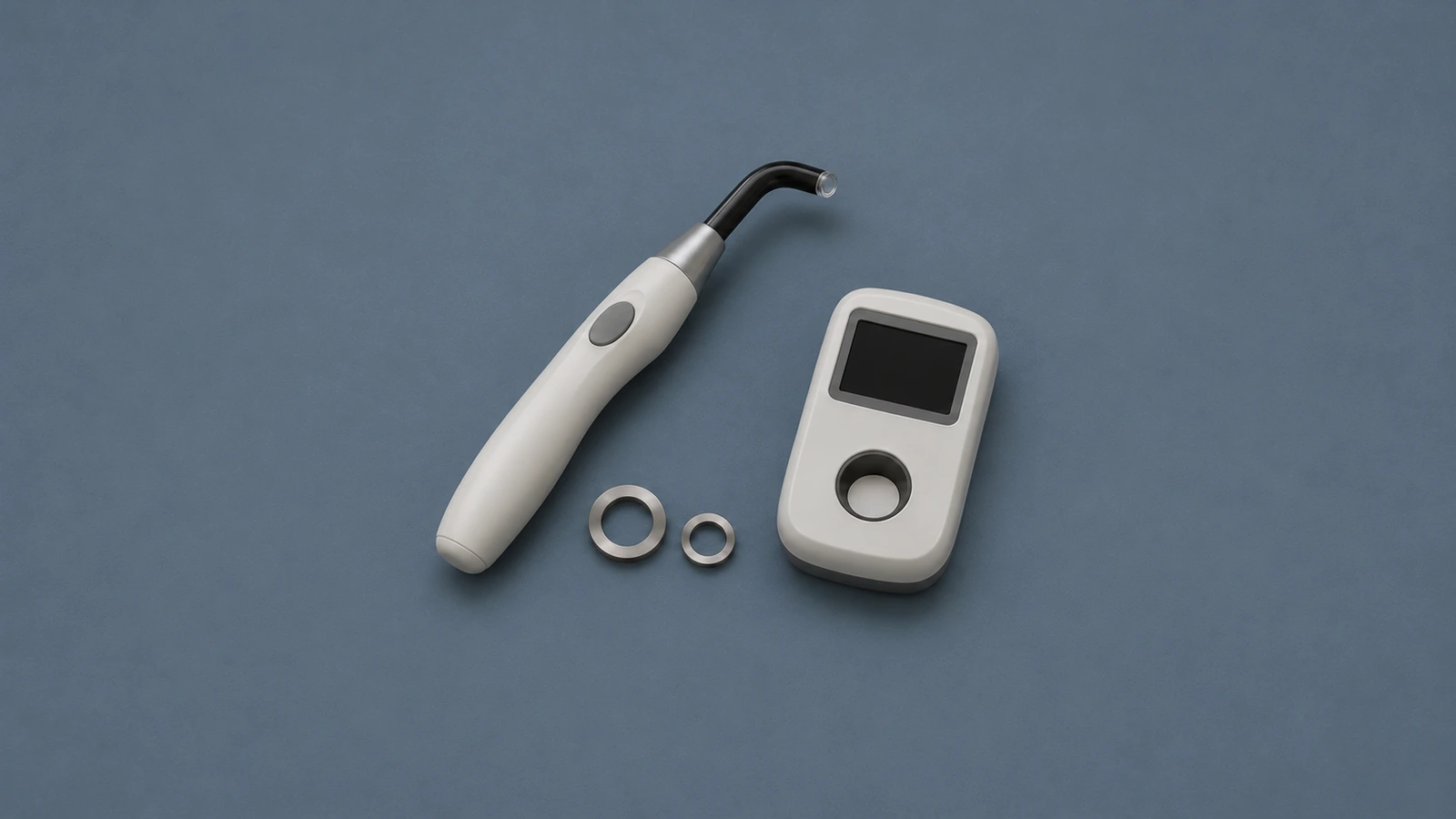
Start with the diameter behind the reading
Suppose two service records for the same dental curing light show 780 mW/cm² and 1,200 mW/cm². Before assigning a fault or accepting an apparent improvement, find the diameter setting, meter identity and measurement mode behind each number. Those readings alone leave the cause of the difference unresolved.
Record captured power in milliwatts (mW), emitting geometry, entered diameter and displayed output per unit area in separate fields. A diameter-dependent display can change when its area denominator changes. Compare records only after checking the meter’s applicable source design, spectral scope and measurement setup. Enter unavailable quantities as unavailable, with the missing evidence identified. The decision here is whether two optical-output records support a meaningful comparison.
Start by retrieving the earlier work order and its attachments. A screenshot of a display may recover the units or program, while a contemporaneous setup record may identify the tip and meter. Keep recovered evidence connected to its original date. If the earlier diameter remains unknown, preserve that gap in the comparison conclusion.
Power and average output per unit area
Power describes optical energy per unit time. A bench instrument captures power through its own collection geometry and spectral response. Treat its reading within that documented scope. Dividing captured power by a justified emitting area produces an area average. At an emitting surface this is average radiant exitance, often called tip irradiance in dental papers and meter documentation. Irradiance at a receiving plane refers to incident power per unit area at that plane. Maucoski, Price and Arrais, 2023
| Record entry | Unit | Basis to retain |
|---|---|---|
| Captured power | mW | Meter power program, collection geometry and spectral applicability |
| Emitting area | cm² | Supported dimensions, shape and method used to establish area |
| Displayed tip-average output | mW/cm² | Meter reading, selected diameter where applicable, and measurement plane |
| Separately calculated average | mW/cm² | Captured power divided by justified area, with inputs and arithmetic retained |
Consider an original arithmetic illustration with a hypothetical captured power of 600 mW. Hold that power fixed and vary only the circular diameter used in the calculation. For diameter d in millimetres, area A = π × (d / 20)² cm² and average output = P / A.
| Hypothetical diameter used | Calculated circular area | Calculated average at 600 mW |
|---|---|---|
| 8 mm | 0.5027 cm² | Approximately 1,194 mW/cm² |
| 10 mm | 0.7854 cm² | Approximately 764 mW/cm² |
The two calculated averages differ because their denominators differ. This example assumes circular geometry and power captured over the corresponding area. Applying it to equipment requires evidence for both inputs. A changed physical light guide also requires a fresh assessment of the actual captured power and geometry. Preserve the meter’s original display alongside any separate calculation so the reader can reproduce the arithmetic.
Read the meter’s permitted measurement mode
Check the applicable instructions for the installed light and meter before interpreting a number. The following examples identify the document versions reviewed. Confirm which instructions govern the actual unit and retain that revision with the work order.
| Documented example | Source and geometry scope | Reading convention |
|---|---|---|
| Bluephase Meter II, 2015-02-27, Rev. 0, 667237/WE3 | 380–550 nm. Circular light guides 6–12 mm support mW and mW/cm². LEDs at the emission window have a 5–13 mm specification for mW only. | The mW/cm² program uses a diameter chosen with the rear template. The IFU specifies centered, flush placement. |
| SDI RADIOMETER X, PAK41400 C | LED curing lights, 400–525 nm, tips up to 12 mm. Published display range is 0–2100 mW/cm². | The display reports the maximum achieved after a 10-second observation. The English instructions give readings in mW/cm². |
The Bluephase document is a historical manufacturer PDF hosted by a distributor. The publication date of the SDI document and the latest-revision status of both examples require confirmation for operational use. Bluephase Meter II IFU, pp. 2–4 and 7 SDI RADIOMETER X IFU, English panel
Ivoclar’s current product page also describes the diameter template and separate mW program. Its advertised ±10% comparison with an integrating sphere is a product accuracy claim. Equipment acceptance still needs the applicable curing-light criteria and a suitable measurement method. Ivoclar product page
Record the capture statistic exactly as documented. The SDI observation duration above belongs to a meter check. Select operating conditions through the applicable instructions. If another meter’s timing or statistic is unclear, seek clarification before comparing its value with a recorded maximum. During testing, follow the manufacturer’s optical-safety precautions, including SDI’s requirement for suitable blue-light filtering eye protection. SDI RADIOMETER X IFU, English panel
Separate measured diameter from the meter input
Three entries can differ on the same work order. Outer diameter describes the physical tip. Active diameter describes the emitting region established by the stated method. Entered diameter is the value actually selected in the meter. Give each a value, unit and evidence basis, or mark it unknown.
In the 2023 experiment, investigators measured internal tip diameter with digital calipers and rounded it to a whole millimetre for Bluephase Meter II input. They explicitly used this approach in place of the meter’s external template. Whole-number input introduces a further distinction between the observed dimension and the selected setting. Maucoski, Price and Arrais, 2023
During service, use the applicable manufacturer method and record it. When comparing a published result obtained by another method, retain that difference in the interpretation. If instructions or area definitions conflict, request clarification from the responsible technical source. An unexplained substitution would leave the comparison without a common basis.
Use the measurement-geometry worksheet
The worksheet below is an editorial synthesis for collecting service evidence. Copy its prompts into a work order and fill them from the actual session. Record an observation, a supporting document or measurement method, a comparison condition and any remaining limitation. “Unknown” and “unavailable on this instrument” preserve useful information when supporting evidence is missing.
| Field | Observed value | Evidence basis | Comparison condition | Unresolved limitation |
|---|---|---|---|---|
| Light identity and documents | Make, model, serial, applicable revision | Nameplate and governing instructions | Identify the same unit and documented configuration | Explain any replacement head or tip |
| Meter identity and documents | Model, serial, applicable revision | Instrument record and instructions | Identify the instrument behind both readings | Record instrument or software changes |
| Meter suitability evidence | Relevant calibration or verification record | Available certificate and manufacturer scope | Establish suitability for this measurement | Identify missing scope or status evidence |
| Tip construction | Light guide, LED at tip, or documented design | Part identification and instructions | Confirm the permitted measurement mode | Resolve unidentified optical design |
| Outer diameter | Value in mm and method | Template, documented measurement or specification | Retain the same dimensional definition | State uncertainty or missing evidence |
| Active diameter or area | Value, unit, shape and method | Applicable technical evidence | Use a supported emitting-area definition | Leave undocumented area unknown |
| Entered diameter | Actual setting in mm, if available | Meter setting recorded during test | Explain any change from baseline | Retain rounding direction and basis |
| Aperture and spectral scope | Documented dimensions and source scope | Meter and light documentation | Confirm applicability to this pairing | Resolve incomplete capture or scope questions |
| Measurement geometry | Plane, separation and alignment | Applicable setup and session record | Reproduce the documented arrangement | Identify missing positioning information |
| Light operating conditions | Selected program and relevant conditions | Light instructions and session record | Compare corresponding operating conditions | Record departures or unknown conditions |
| Capture convention | Statistic and observation timing | Meter instructions and session record | Compare corresponding statistics | Clarify an undocumented display algorithm |
| Accessories and barriers | Configuration present during measurement | Session record and applicable instructions | Retain comparable accessory conditions | Seek documented guidance for a change |
| Native displayed values | mW and mW/cm² as available | Unaltered readings with units | Preserve each program’s original result | Mark unavailable power explicitly |
| Separate calculations | Inputs, area, formula and result | Reproducible calculation record | Label each derived quantity | Carry input limitations into the result |
| Baseline and acceptance reference | Earlier work order and applicable criteria | Dated record and governing document section | Establish the comparison and decision basis | Identify absent criteria or baseline details |
| Open items and reviewer | Missing evidence, owner and next action | Work-order review record | Make the pending decision explicit | Retain referral and follow-up details |
| Comparison decision | Comparable setup, repeat documented setup, or insufficient evidence | Completed worksheet and reviewer assessment | Record the basis for the selected outcome | Assign clarification or referral when evidence is insufficient |
Use these prompts to explain comparison eligibility. A record with consistent, supported conditions can contribute to a trend. Where a controllable condition differed, repeat under the applicable documented setup and retain both observations. Where source applicability or area remains unresolved, obtain clarification or an appropriate measurement before assigning an output conclusion.
For example, an older record may contain only mW/cm², while the new meter offers both programs. Preserve the new mW reading as new evidence and state that the historical power value is unavailable. Back-calculating power from the older display would require its area and measurement basis. Without those inputs, the older record supports a narrower comparison.
Likewise, if the current diameter setting differs from the baseline, document both settings and why the change occurred. Retain the relevant manual revision or correction record. A later reviewer should be able to distinguish a documented method change from an observed equipment-output change.
Interpret disagreement before assigning a fault
The 2022 power study compared two units from each of 12 curing-light brands using two radiometer brands and an integrating-sphere reference. It found useful agreement within the tested measurement scope. Bluephase Meter II substantially overestimated the broad-spectrum PinkWave output, and those readings were excluded from its regression. The authors attributed that mismatch to emission extending beyond the meter’s range. Their results support checking the particular source–meter pairing and retaining experimental limitations when interpreting agreement. Maucoski and colleagues, 2022
The 2023 irradiance study found Bluephase Meter II useful for most tested brands under its internal-diameter protocol, while accuracy varied across light–meter pairings. Its scope included two units per brand, standard settings and manual positioning. Those conditions bound the findings. Maucoski, Price and Arrais, 2023
Shortall, Hadis and Palin’s 2021 study describes how detector aperture, source area, spectral response and beam nonuniformity can affect readings. Most meter models had one specimen. The authors also support standardized monitoring of an individual curing light with the same radiometer to detect decline. Shortall, Hadis and Palin, 2021
Use those findings to work through the record. First resolve changed settings and setup. Then resolve applicability questions. If a concern persists with a suitable instrument under the documented procedure, retain the repeated results and refer the evidence through the applicable service channel. Describe the finding as a repeatable output concern until fault-isolation evidence supports a component diagnosis.
Write a conclusion the evidence supports
A useful conclusion names the tested unit, tip, instrument, setup, result and reference. Connect the worksheet to the main work order so the next technician can recover the original observations. Where calibration documentation is available, link its identifier to that instrument’s record. Service-record guidance · Calibration-certificate review
A record template can read as follows. “Checked [light model and serial] with [tip identification] using [meter model and serial] under [procedure and revision]. Recorded [available mW] and [displayed mW/cm²], using [diameter setting and basis] at [documented geometry and operating conditions]. Compared with [baseline work order and applicable acceptance reference]. Outstanding evidence is [gap], assigned to [responsible reviewer] for [next action].”
Equipment acceptance requires the applicable device criteria, required checks and responsible reviewer’s decision. The comparison worksheet supplies evidence for that process. Choose any numerical acceptance limit from the governing equipment reference and retain its source beside the result.
A momentary radiometer value has limited clinical interpretability. Shortall and colleagues explain that selecting exposure time for a particular material and light requires additional evidence. Leave restoration assessment and clinical curing decisions with the responsible dental team and applicable product instructions. Shortall, Hadis and Palin, 2021
For suspected meter defects, the reviewed Bluephase IFU assigns repairs to certified Ivoclar service centers, and the SDI IFU assigns repairs to SDI-authorized personnel. Follow the installed equipment’s applicable service route and provide the recorded conditions and unresolved questions with the referral. Bluephase Meter II IFU, pp. 2–4 and 7 SDI RADIOMETER X IFU, English panel