
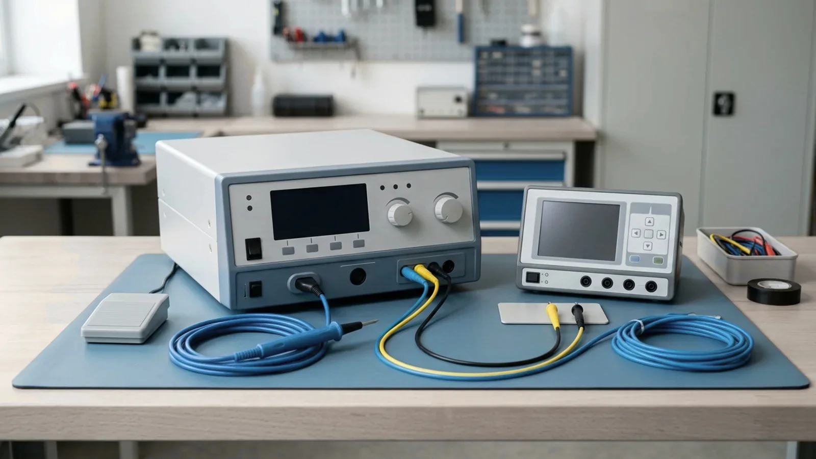
Short answer: treat each labeled output mode as a separate test. An electrosurgical unit (ESU) turns mains power into high-frequency current that heats tissue to cut or coagulate it. The 2016 field study discussed below notes that generators raise the output frequency above 200 kHz so the current can pass through the patient with minimal nerve and muscle stimulation. The modes then shape that energy differently over time. A generator can be correct in one mode and wrong in another, and a single reading cannot tell the two apart.
A common bench shortcut is one pure-cut power reading into a nominal load plus a mains leakage check. That combination exercises one output path at one operating point. It does not show whether the blend timing, the high-voltage coagulation outputs, the bipolar output, HF leakage or the return-electrode monitor perform as the manufacturer specifies. CMS S&C 14-07-Hospital states that equipment must be inspected and tested for performance and safety before initial use and after major repairs or upgrades. For an electrosurgical generator, that means evidence for each mode the unit offers clinically.
graph TD
  A["Service event: initial use, scheduled PM or major repair"] --> B["Collect acceptance sources: service manual, IFU output curves, standard edition if specs are unavailable"]
  B --> C["Mains electrical safety per the IEC 62353 procedure"]
  B --> D["Each labeled mode: power at specified loads and settings; current, peak-to-peak voltage, crest factor; waveform vs manual"]
  B --> E["HF leakage matched to ground-referenced or isolated output"]
  B --> F["Return-electrode monitor: alarm and activation inhibit"]
  B --> G["Fitted options: vessel sealing, impedance sensing, inert gas"]
  C --> H{"Every mode and check within manufacturer limits?"}
  D --> H
  E --> H
  F --> H
  G --> H
  H -- "Yes" --> I["Record per-mode evidence and release"]
H -- "No" --> J["Hold, correct, retest; escalate per manufacturer"]What the Output Mode Changes
The field study gives a plain description of the three basic current types. A cutting current is a continuous, uninterrupted sinusoidal waveform with high average power and high current density. A coagulation current consists of high-voltage, relatively low-current intermittent bursts of damped sine waves. A blended current runs at voltages between the two, and its off-period sets how much hemostasis comes with the cut. Within coagulation, desiccation is a contact technique, while fulguration is a non-contact technique that relies on a spark across an air gap.
Those differences are why power alone is a weak check. Crest factor is the ratio of a waveform's peak voltage to its root-mean-square (RMS) voltage:
Crest factor = V_peak / V_rms
A continuous sine wave has a crest factor of √2, about 1.41. An interrupted waveform that delivers its energy in short bursts has a higher peak relative to its RMS value, so its crest factor rises as the duty cycle falls. Two modes can deliver the same average power with very different waveforms. That is why FDA's 510(k) guidance for electrosurgical devices asks manufacturers to document, for each mode, the waveform's amplitude, frequency, duty cycle, load and crest factor. It is also why Fluke Biomedical's ESU testing best practices suggest comparing the actual wave shape with the one in the service manual.
The current path also differs. In monopolar mode, current flows from the active electrode through the patient to a return electrode and back to the generator. In bipolar mode, both electrodes sit at the instrument tip, usually forceps, and the study notes that most bipolar outputs use a lower-voltage waveform with more limited thermal spread. Bipolar therefore needs its own loads and settings from the service manual; it cannot borrow the monopolar results.
Output topology matters as well. The study describes ground-referenced generators, where current can return through any grounded object touching the patient, such as ECG electrodes, the table or staff. Isolated generators, developed in the early 1970s, route current back through the return electrode to an isolation transformer inside the generator, and the return electrode is not referenced to ground. A technician needs to know which design is on the bench before choosing an HF leakage method and limit.
Finally, keep HF verification separate from mains electrical safety. Our guide to electrical safety testing after repair covers IEC 62353 and NFPA 99 checks of 50/60 Hz leakage current and protective-earth resistance. Those checks are needed here too, but they do not exercise the generator's high-frequency output, its waveform control or its return-electrode monitor.
The Mode-Matched Test Set
Table 1 maps each output or safety function to the bench evidence it needs and to the place its acceptance value should come from. It deliberately contains no numeric limits. Those belong to the specific generator's service documentation, or to the named standard edition when that documentation is unavailable.
| Output or function | What differs | Bench evidence to capture | Acceptance source |
|---|---|---|---|
| Pure cut | Continuous, uninterrupted sine waveform with high average power | Power, current, peak-to-peak voltage and crest factor at the nominal load and at loads across the manufacturer's stated range; waveform compared with the manual | Service manual; IFU power-versus-load curves |
| Blended cut (each blend setting) | Cut waveform interrupted by off-periods that set the degree of hemostasis | The same measurements for every blend setting offered; burst envelope compared with the manual | Service manual; IFU |
| Contact coagulation (desiccation) | Higher-voltage, lower-current intermittent bursts applied in tissue contact | Power, peak-to-peak voltage and crest factor at the loads the manual specifies | Service manual; maximum output voltage stated in the IFU |
| Spray coagulation (fulguration) | Non-contact, high-voltage waveform that arcs across an air gap | Power, peak-to-peak voltage and crest factor at the specified loads; HF leakage in this mode where the procedure calls for it | Service manual; IFU maximum output voltage |
| Bipolar | Both electrodes at the instrument tip; lower-voltage waveform | Power at the bipolar loads and settings the manual specifies, using the analyzer's bipolar connection | Service manual |
| Vessel sealing or impedance-sensing output (where fitted) | Generator adjusts output in response to the load it sees | The manufacturer's vessel-sealing check; power-distribution or vessel-sealing measurement across the specified loads | Manufacturer procedure |
| HF leakage | Behavior depends on ground-referenced versus isolated design | Leakage from the active and neutral outputs using the specified layout, with topology recorded | Manufacturer; IEC 60601-2-2 maximum levels and layout |
| Return-electrode monitor (CQM/RECM) | Contact-quality monitoring differs from simple cable-continuity monitoring | Audible and visual alarm plus activation inhibit, demonstrated under the manufacturer's test conditions, with trip values recorded | Service manual; the generator's monitoring design |
| Inert-gas (argon) option | Gas envelope at the surgical site | Gas flow and pressure | Service manual |
| Mains electrical safety | 50/60 Hz quantities, not high-frequency output | Ground-wire resistance and chassis leakage as a separate IEC 62353 activity | Manufacturer; IEC 62353 procedure |
Loads and Settings: Moving Beyond the Nominal Point
FDA's guidance recommends that a manufacturer's premarket submission include, for each mode, a graph of the output waveform at rated load identifying the mode, amplitude, frequency, duty cycle, load used and crest factor. It also recommends a graph of power output at maximum and half-of-maximum intensity over the range of expected loads, giving 100 Ω to 2000 Ω for monopolar as an example. FDA asks for these curves to come from measured data rather than theoretical values.
That template describes manufacturer type testing, not a hospital service procedure, and it does not bind a service shop. It does show what a meaningful power check looks like. Where the service manual specifies loads and settings, use exactly those. Where it doesn't, test each mode at the manufacturer's nominal load plus loads toward each end of the stated range, at maximum and at an intermediate setting such as half of maximum, and record why those points were chosen. The 2016 field study used three loads per mode at the maximum output setting, with the nominal load chosen from the manufacturer's instructions. Fluke describes the purpose of the multi-load power-distribution test: to show whether the impedance-sensing circuits of newer generators keep the output from falling as the presented load changes.
If the service manual is missing, the operator's manual may still hold the expected values. FDA's labeling recommendations ask manufacturers to include, for each output mode, graphs or tables of actual power output under a specified impedance for each intensity setting, graphs of power at maximum and half-maximum across the expected impedance range, and the maximum output voltage. Record which document and revision supplied the expected values.
HF Leakage: Grounded Versus Isolated Outputs
Fluke describes RF leakage as a critical parameter because it can cause accidental patient burns, and notes that IEC 60601-2-2 sets the maximum RF leakage levels and defines the measurement elements and their layout. The field study explains the mechanism: when current has a grounded path other than the return electrode, it can leave the patient at that point. Two design cases follow:
Ground-referenced generators: Expect these to be the harder test. In the 2016 study, most ground-referenced units exceeded the HF leakage limit the authors applied (details below). The authors state that HF leakage depends on the facility's earthing resistance and recommend checking the quality of the hospital's earth system before testing the unit.
Isolated generators: The return electrode is not referenced to ground, so alternate-site current paths are reduced, but leakage is still measured and recorded. Confirm that the analyzer supports isolated as well as grounded equipment. Fluke's QA-ES III product page, for example, states that it measures HF leakage from both.
Lead layout affects the reading. Fluke advises keeping all test and interconnecting leads as short as possible and never crossing or coiling measurement leads. RF energy radiates and induces current in nearby conductors, so long leads behave more like antennas than test leads. Record the layout and analyzer settings so a later retest can be compared with this one.
Return-Electrode Monitoring: Prove the Alarm and the Inhibit
FDA's guidance draws a distinction worth keeping on the work order. A contact quality monitor (CQM) watches the contact between the neutral electrode and the patient and alarms if the contact becomes insufficient and the patient is at risk of burns. A continuity monitor only checks the connection between the neutral electrode and the generator; it alarms if the connection is lost but cannot detect a high current density at the electrode. Fluke describes the return-electrode monitor as a watchdog that alarms audibly and visually and stops the generator from energizing once its threshold is exceeded.
The trip values belong to each generator's monitoring design. Even in premarket testing, FDA notes that the methods vary with the monitoring design. Use the manufacturer's procedure, with the analyzer's CQM function or the resistance values the service manual specifies. Record where the alarm occurred and confirm the generator refused to activate while the alarm was active. Don't borrow a threshold from another model.
Accessory compatibility completes this check. FDA recommends that labeling for a generator with a CQM warn that losing safe contact will not trigger an alarm unless a compatible monitoring neutral electrode is used. IEC 60601-2-2 Edition 6.1 adds a requirement for adult neutral electrodes to be contact quality monitoring neutral electrodes. That is a product-conformity requirement, not a hospital stocking rule. It is still a good reason to confirm that the return electrodes stocked for each generator are compatible monitoring types.
What Requires the Tests and When
CMS: Before Initial Use and After Major Repairs
The hospital Condition of Participation at 42 CFR 482.41(c)(2) states that facilities, supplies and equipment must be maintained to ensure an acceptable level of safety and quality. CMS S&C 14-07, dated December 20, 2013, revised the interpretive guidelines for that requirement (Tag A-0724). Several points apply directly to electrosurgical generators:
Initial use and major repairs: "All equipment must be inspected and tested for performance and safety before initial use and after major repairs or upgrades." Whether a particular board replacement counts as major is a documented decision. Our guide to major repair return-to-service testing covers how to make it.
Manufacturer activities: A hospital complies when it follows the manufacturer-recommended maintenance activities and schedule. It must keep documentation of those recommendations and of the maintenance actually performed.
Test equipment: Tools used for maintenance need not be the ones the manufacturer recommends, but they must be capable of providing results equivalent to those the manufacturer requires.
Alternate equipment management (AEM): A hospital may use risk-based alternatives with documented rationale, but it must identify "critical equipment", meaning equipment whose failure risks serious injury or death, and surveyors focus their AEM review there. New equipment without enough maintenance history must follow manufacturer recommendations, and imaging or radiologic equipment and medical lasers are not eligible. Electrosurgical units are not among CMS's named ineligible examples, although other federal or state law can still require manufacturer-based maintenance. AEM, though, adjusts scheduled maintenance activities and frequencies. It does not override the separate expectation to test before initial use and after major repairs.
On intervals, Fluke reports that most major electrosurgical manufacturers recommend semi-annual preventive maintenance. It also cites a risk-based method from J. Tobey Clark's Medical Equipment Quality Assurance that recommends testing every six months. The 2016 study's authors argue for verification at least annually. Under the CMS guidance, the manufacturer's own recommended activities and schedule apply unless a documented AEM decision changes them.
IEC 60601-2-2 Edition 6.1: What the 2026 Recognition Changes
On May 25, 2026, FDA entered IEC 60601-2-2 Edition 6.1 2023-02 Consolidated Version, Corrected Version 2025-11 as recognition 6-521 on Federal Register recognition list 066. The extent of recognition is the complete standard, and the entry is included in FDA's ASCA program. It supersedes recognition 6-389 of Edition 6.0 (2017-03). FDA will accept declarations of conformity to Edition 6.0 in premarket submissions until July 1, 2029. The IEC webstore listing confirms the same publication state: IEC 60601-2-2:2017+AMD1:2023 consolidated version, corrected version 2025-11, which includes interpretation sheet 1.
The published scope covers the basic safety and essential performance of HF surgical equipment and HF surgical accessories. HF surgical equipment with a rated output power not exceeding 50 W, for example for micro-coagulation or for use in dentistry or ophthalmology, is exempt from certain requirements, and the relevant clauses identify the exemptions. The sixth edition's listed technical changes are refined and added definitions, further separation of requirements for equipment and accessories, a new requirement for adult neutral electrodes to be contact quality monitoring neutral electrodes, and new requirements for devices that have or use a high current mode.
For a service shop, three practical points follow. First, recognition supports manufacturers' premarket declarations; it does not by itself impose new test requirements on hospital service programs, and the 2029 date concerns premarket declarations. Second, a fleet will include generators designed to earlier editions; the 2016 study, for instance, cites the 2009 fifth edition. A unit's acceptance values come from its own manufacturer documentation, and the standard edition matters mainly when those specifications are unavailable, so record which edition you used. Third, FDA warns that IEC 60601-2-2 includes general methods with multiple options and in some cases no acceptance criteria. "Tested to IEC 60601-2-2" means little unless the record states the method, loads and limits actually applied. Fluke likewise treats the IEC requirements as "a reasonable substitute" only when manufacturer specifications are not known.
What Field Testing Found
A generator that powers up without an error code and responds to the footswitch can still be out of specification. The 2016 study in the Journal of Biomedical Physics and Engineering tested 20 electrosurgical units in clinical use: four brands and three models across six hospitals (three public and three private) in one province of Iran. The hospitals said none of the units had been analyzed recently, and technical histories were incomplete. The measurement setup was designed in accordance with IEC 60601-2-2, using a Fluke biomedical analyzer for output power and HF leakage and a Fluke electrical safety analyzer for patient leakage current.
| Finding | Result | Context |
|---|---|---|
| Output power | Only 8 of 20 units delivered acceptable output values | Deviation from the manufacturer's disclosure was graded as 10–20%, 20–30% or above 30%; the authors also report low measurement precision |
| HF leakage, ground-referenced units | 9 of 13 outside the limit | The study's table lists a 150 mA maximum, from the standard edition it cites (2009) |
| HF leakage, isolated units | 7 of 7 within the limit | Same method and limit as the ground-referenced units |
| Patient leakage current (general electrical safety) | 6 of 20 outside limits | Tested under the general standard, IEC 60601-1 |
| Bipolar power analysis | Not performed on 5 units | The authors note that operating-room workload limited testing time and the parameters checked |
Power was measured for each operating mode (monopolar cut, coagulation and blend, plus bipolar) at the maximum output setting into three loads, one of them the manufacturer's nominal load. Following IEC 60601-2-2, the authors note that each operating mode has an appropriate output power range that should be specified in the technical manual and kept within acceptable limits. They also link HF leakage to facility earthing resistance in their discussion. That is an explanatory statement by the authors, not a separately measured correlation.
Read the numbers with their limits in mind. This was a small, single-region sample, published in 2016, tested against the standard edition then in force; it is not US incidence data. The study's parameter list included return-electrode monitoring and audible-signal checks, but its results table reports only output power, HF leakage and patient leakage. What the study does show is that units in routine use, with no recent analysis on record, were outside manufacturer power disclosures and leakage limits while still in service. Mode-by-mode verification exists to catch exactly that.
Analyzer Capability and What a Pass Does Not Prove
CMS requires test equipment capable of results equivalent to the manufacturer's requirements. For an ESU, that means an electrosurgery analyzer that can reproduce the loads and measurements in the service manual. An electrical safety analyzer measures mains-frequency quantities such as ground-wire resistance and chassis leakage; the field study likewise used a separate electrical safety analyzer for patient leakage current.
Fluke's product page for the QA-ES III gives a sense of the capability to look for, though as a vendor claim rather than independent verification. It lists continuous measurement of power, current, peak-to-peak voltage and crest factor; testing of impedance-sensing circuitry in power-guarantee functions; HF leakage from grounded and isolated equipment; contact quality monitor testing; vessel-sealing measurement; and output power distribution, with accessory leads that include a CQM safety lead, an RECM alarm-disabling lead and a bipolar activation lead. Before relying on any analyzer, check that it offers the loads your service manual specifies, a bipolar connection, CQM testing, HF leakage for both topologies and vessel-sealing measurement if the fleet needs it. Also check that its calibration is current; our guide to auditing a calibration certificate covers what to look for.
Be precise about what a passing run establishes:
What a pass shows: At the tested settings and loads, the generator delivered output within the manufacturer's tolerance into the analyzer's resistive loads. Its waveform and crest factor matched the service manual, leakage stayed within the applicable limit in that bench layout, and the return-electrode monitor alarmed and inhibited activation under simulated conditions.
Tissue effect is a separate question: Bench loads are fixed resistances, whereas clinical loads vary with tissue and over the course of an activation. FDA's guidance notes that premarket testing may need in vivo or ex vivo animal models, and asks sponsors to explain the clinical relevance of acceptance criteria for any tissue-effect test. A bench pass is not clinical validation.
Accessories are outside the test: Active electrodes, cables and return electrodes are not covered by a generator pass. FDA asks manufacturers to address leakage through insulation and capacitive coupling, and recommends a labeling warning against hybrid metal-and-plastic trocar systems with monopolar components because of the risk of alternate-site burns.
A standard reference is not a method: Because IEC 60601-2-2 offers multiple method options and sometimes no acceptance criteria, a pass means only what the record says was done.
The same boundary applies to defibrillator energy verification: a fixed analyzer load confirms the device's delivered output, not the patient's response.
Recording the Evidence Before Return to Service
The CMS interpretive guidance at Tag A-0724 expects documentation of the manufacturer's recommendations and of the maintenance actually performed, and an equipment inventory with identifiers such as manufacturer, model and serial number. A record that says only "PM complete, passed" does not let a reviewer reconstruct which modes, loads or limits were used. An electrosurgical work order should carry the following:
Device and service event: Asset identifier, manufacturer, model, serial number and software or firmware revision where displayed. State the trigger (initial use, scheduled maintenance or corrective repair) and list any replaced assemblies.
Procedure and acceptance source: The service manual title and revision, the IFU output curves or, if manufacturer specifications were unavailable, the standard edition used. Fluke recommends that once inspection criteria are agreed, any change carries a rationale statement explaining why it was needed and how it was validated.
Analyzer and tools: Model, serial number, calibration status and due date for the electrosurgery analyzer and the electrical safety analyzer.
Per-mode output results: For each labeled mode and setting tested, record:
The mode, the setting (for example maximum and half-maximum) and each load used.
Measured power against the expected value and tolerance.
Current, peak-to-peak voltage and crest factor, plus the result of the waveform comparison with the manual.
HF leakage: Output topology (ground-referenced or isolated), measurement points, measured values, the applicable limit and its source.
Return-electrode monitor: The values at which the alarm occurred, confirmation that activation was inhibited, and the return-electrode type used for the test.
Fitted options: Vessel-sealing or impedance-sensing results, and inert-gas flow and pressure where the unit has that option.
Mains electrical safety: Results from the IEC 62353 procedure your program uses, recorded as a separate test.
Disposition: A pass or fail for each mode and check, the release decision, the technician and the date. Treat any failed mode as a failed unit: hold it, correct the fault, retest, and escalate to the manufacturer when the fault cannot be resolved within the service procedure.
For the wider documentation standard, including how these fields fit a CMMS work order, see our guide to medical equipment service record requirements. With per-mode evidence and a named acceptance source for each value, a release decision can be reconstructed and defended later.