
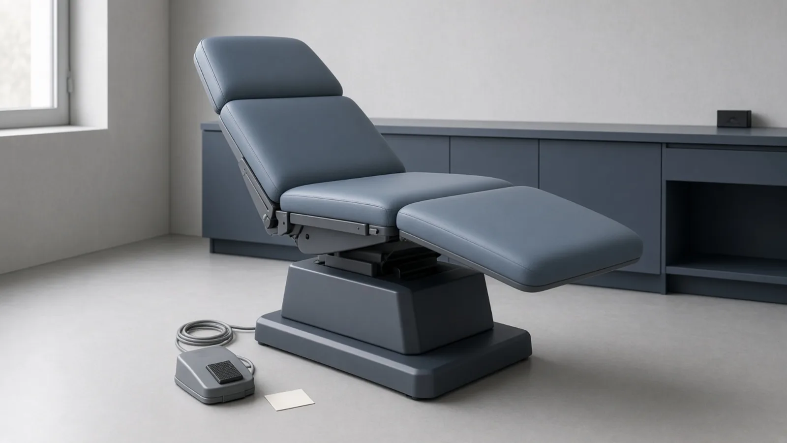
When a powered examination table or procedure chair stops moving in an active clinical suite, clinic operations stall immediately. Providers face canceled outpatient procedures, room scheduling bottlenecks, and immediate revenue losses. In the rush to restore clinical capacity, clinical teams frequently dispatch service requests with vague, single-sentence descriptions such as 'table dead' or 'chair beeping and will not adjust.' What follows is a predictable cycle of wasted time: an independent service organization (ISO) or original equipment manufacturer (OEM) field engineer arrives blind, spends billable diagnostic hours troubleshooting an unlatched base interlock or an overloaded accessory outlet, or discovers that the specific actuator or control board needed for that exact serial generation is not on the truck.
A defensible, professionally managed service event requires a structured repair handover package. Ten minutes of operator-safe triage at the chairside separates self-clearing mechanical interlocks from genuine component hardware failures. When hardware failure is confirmed, assembling a technical handover—serial generation, the green and red display codes copied exactly, stored-error history from a qualified servicer, and which axes still move—gives the service provider something to quote against. Before the table returns to patients, healthcare technology management (HTM) should read the itemized quote for parts provenance under FDA's May 2024 remanufacturing guidance. A CMS-certified hospital also needs the performance and safety inspection Tag A-0724 describes after a major repair.
Why a powered exam table is medical electrical equipment, not furniture
A common administrative error in outpatient clinics and ambulatory surgical centers is treating powered examination tables as facility furniture rather than medical electrical (ME) equipment. Facilities staff often route table service requests through generic building maintenance work-order queues, bypassing the healthcare technology management team entirely. This administrative misclassification leads to dangerous practices, including unverified third-party motor substitutions, uncalibrated limit switches, and skipped electrical safety verification.
The regulatory boundary is narrow. Under 21 CFR 880.6140, FDA identifies a medical chair or table as a device without wheels and not electrically powered, intended for blood donors, geriatric patients, or patients undergoing treatment or examination. That category is Class I. It is exempt from premarket notification, subject to the limitations in 21 CFR 880.9, and exempt from the current good manufacturing practice requirements of the quality management system regulation in 21 CFR 820, except for records and complaint files under 21 CFR 820.35. The exemption stops at that non-powered identification. This article does not assign an FDA class to an electrically powered procedure table.
A motorized, multi-articulating table is outside the identification in 21 CFR 880.6140(a). That fact alone does not certify it to any one electrical standard. The compliance chart this article can cite is in Midmark's legacy user guide, document 003-1407-00 Rev. Z, for models 630 (-001 through -009). That chart lists:
UL 60601-1, the general medical electrical equipment standard named on that legacy chart.
CAN/CSA C22.2 No. 601.1-M90, the Canadian standard named on the same chart.
IEC 60601-1, the international general standard named on the same chart.
EN 60601-1-2, the EMC standard named on the same chart.
Electrical Class 1 and a Type B applied part, which is how that chart classifies the patient-contacting surface. The label sets the protection class in the standard.
IPX1 on the foot control, the fluid-ingress mark that chart prints for the foot control.
Those marks belong to the legacy 630 chart. They are not a certificate for every powered exam table, and they are not evidence about a later serial generation. When the label on the chair in the room says it is medical electrical equipment, the repair belongs on a clinical engineering work order. After a motor, control-board, or structural repair, return to patients needs the performance and electrical safety evidence the facility already requires for other mains-powered medical equipment.
First ten minutes: operator-safe checks before anyone is called
Before generating a service dispatch or calling an external service vendor, clinic staff and biomeds should perform a systematic, operator-safe triage protocol. Modern powered tables incorporate multiple safety interlocks designed to inhibit motion under hazardous conditions. In clinical practice, these protective interlocks frequently mimic catastrophic power supply or motor drive failures, leading to unnecessary service calls and prolonged room downtime.
The initial operator evaluation follows four logical steps that can be completed chairside in less than ten minutes without opening internal chassis enclosures:
Step 1: Facility and Mains Power Verification. Verify that the table power cord is firmly seated in the Power Entry Module (PEM) at the base of the table and plugged into a live wall receptacle. Check whether adjacent equipment powered by the same branch circuit is operational. If the outlet is dead, reset the facility circuit breaker or ground-fault circuit interrupter (GFCI). Inspect the main power switch on the table's power entry module to ensure it is switched to the ON position.
Step 2: Legacy inlet fuses only. On Midmark 630 models -001 through -009, the user guide tells the operator to disconnect the power cord, inspect inlet fuses F1 and F2 (6.3 A, 250 V, Type T), and confirm the voltage-setting window matches the facility supply. On the current 630 troubleshooting chart, F1 and F2 are on the power supply circuit board. That check belongs to a qualified servicer.
Step 3: Accessory receptacle, read by generation. The legacy 630 user guide limits the optional duplex receptacle to 3 A combined and says an overload blows fuses and disables all functions. Unplug accessory loads and see whether motion returns. On the current troubleshooting chart, a dead receptacle while other functions still work points to the chair circuit breaker at the base, reset by pressing it. That row is not control lockout.
Step 4: Mechanical Safety Interlock Clearance. Inspect the physical status of the four primary motion-inhibiting safety interlocks documented below.
Mechanical interlocks generate specific operational symptoms that are easily mistaken for hardware component failures:
Treatment pan: The current foot-function page says the pan switch stops foot motion when the pan is pulled out, and machine-control code 01-16 is Treatment Pan Out. Stow the pan completely. The legacy user guide adds that this condition disables Foot Up and beeps. Foot-function code 16 on the current chart is a different fault, I2C slave not initialized.
Rotation base: The current foot-function page states that none of the actuator motors will run if the optional rotation base is unlocked. Lock the base and try the motion again. That operating interlock is separate from machine-control code 01-15, which means the rotation brake switch was detected pressed during power-up. On the legacy user guide, the rotational base auto-locks after two minutes.
Control lockout: On the current 630 chart, a button press during lockout produces three beeps and no motion, and the code is 01-14. Press and hold Stop and Back Down together for two seconds. One beep means lockout is disabled.
Floor clearance and obstructions: On legacy models -001 through -009, the user guide says the crash avoidance system beeps and disables Base Down, Back Down, and Tilt Up when the headrest mechanism is about two inches from the floor. On the current chart, Active Sensing is a different code family: machine-control 01-07 is headrest clearance, 01-08 is back-cover clearance, and 01-09 is foot clearance, while axis code 07 means Active Sensing has tripped. Clear stools, cords, and foot controls from the descent path. Do not record this behavior as code 12. On the machine-control table, 12 is low voltage at 48 VDC. On the axis tables, 12 is a memory-save error.
Capturing fault evidence the vendor can act on
If operator-safe checks confirm that power is intact, receptacles are unloaded, and all safety interlocks are cleared, but the table remains inoperative, the handover package must be assembled. When dispatching a repair request to in-house HTM or an external ISO, providing structured technical evidence eliminates preliminary diagnostic trips, ensures that replacement actuators or control boards are ordered correctly, and creates an audit-ready service trail.
A complete, professional repair handover package contains five core technical packages:
1. Complete Asset Identity and Serial Generation: Record the manufacturer, full model number, exact serial number, and electrical configuration (115 VAC vs. 230 VAC). Crucially, capture the serial number prefix or suffix (for example, Midmark 630-001 through -009 versus current serial production). The same model name spans generations with different control boards, actuators, and wiring harnesses.
2. Attached Accessories Inventory: List all controls and hardware currently connected to the table. Specify whether the table utilizes a corded hand control, a corded multi-pedal foot control, a wireless foot switch, or dual redundant controls. Note the presence of articulated headrests, pull-out stirrups, pelvic tilt options, and heated upholstery.
3. Display code, copied exactly. On the current 630, document 630-SR-00048, the green display is the function or system and the red display is the fault. The page's own example is green 02 for Base and red 09 for a switch error. Green 01 is the machine control board. Red codes use hexadecimal digits (0A, 0b, 0C, 0d, 0E, 0F), and the manual warns that some digits look alike. Photograph a code that is already visible. Do not open the enclosure to hunt for the display, and do not translate a hex code into a decimal guess. Axis meanings and machine-control meanings differ: on the axis tables, 09 is a limit switch, 0C is motor current, and 0E is motor stall, while on the machine-control table 09 is foot clearance and 14 is control lockout.
4. Stored-error history, from a qualified servicer. The same document keeps the last ten errors, newest first. Recall is a board-level procedure: power is removed, S2 switches 3 and 4 are set on, power is restored, and S3 is pressed and released. A beep marks each displayed error, the display shows FFFF when fewer than ten errors are stored, and three beeps mark the end of a full list of ten. Ask the servicer to record that sequence. Clinic staff should not unplug the chair to move board switches.
5. Functional Symptom Profile and Usage Context: Document which individual axes respond to commands and which controls trigger motion. Does the hand pendant work while the foot pedal is dead? Does the motor hum or run continuously without moving the chair? Record recent operational context: Was the chair operated under continuous back-to-back procedures violating the manufacturer's duty cycle (e.g., legacy Midmark 30 seconds on / 5 minutes off)? Were heavy accessories or bariatric patients positioned on the table?
A model-scoped fault and escalation map (worked example: Midmark 630)
To illustrate how chairside fault evidence translates into service decisions, the following model-scoped diagnostic map details the Midmark 630 Universal Procedures Table platform. This worked example maps specific physical symptoms and electronic error codes to chairside triage and professional service escalation.
flowchart TD
    A["Table Inoperative or Beeping"] --> B{"Whole Table Dead or Single Axis?"}
    B -->|"Whole Table Dead"| C["Check outlet, facility breaker, and the fuse or breaker the manual names"]
    B -->|"Beeping on Command"| D{"Check Interlock Status"}
    B -->|"Single Axis Inoperative"| E["Inspect Axis Control & Record Digital Code Pair"]
    D -->|"3 Beeps on Press"| F["Control Lockout Active: Hold Stop + Back Down 2s"]
    D -->|"Foot Up Disabled"| G["Treatment Pan Extended: Fully Stow Pan"]
    D -->|"All Axes Inactive"| H["Rotation Base Unlocked: Engage Brake Pedal"]
    D -->|"Base/Back Down Blocked"| I["Floor Proximity / Active Sensing Obstruction"]
    C --> J{"Power Restored?"}
    J -->|"Yes"| K["Resume Clinical Use"]
    J -->|"No"| L["Dispatch Qualified Biomedical Service"]
    F --> K
    G --> K
    H --> K
    I --> K
    E --> L
    L --> M["Qualified servicer records serial generation and stored-error history"]
    M --> N["Require Itemized Quote: OEM vs Aftermarket Parts Provenance"]
N --> O["Post-Repair Return Testing: Controls, Interlocks, Ground & Leakage"]Midmark 630 Diagnostic and Escalation Matrix
| Symptom Class | Display / Error Code | Operator-Safe First Checks | Qualified Servicer Escalation |
|---|---|---|---|
| No functions operate, and the chair receptacles are dead (current 630 troubleshooting chart) | No error code. The display is unpowered. | Confirm the cord at the wall and at the power entry module, and whether the facility breaker for that outlet is on. On legacy models -001 through -009 only, with the cord unplugged, inspect inlet fuses F1 and F2, 6.3 A, 250 V, Type T, and the voltage window. | The current chart directs a qualified servicer to test F1 and F2 on the power supply board, the wiring from the power entry module, and the power toroid. The foot-function page describes 115 VAC through those fuses, a toroid secondary of 25 VAC, and +24 VDC and -24 VDC through F3 and F4 on the way to the motor hub. Leave that measurement with the qualified servicer. |
| Receptacle dead while other functions still work (current chart) | The chart does not assign this row code 01-14. | Unplug accessory loads. If the base has the chair circuit breaker the chart describes, press it to reset. | Check the receptacle wiring at J11 on the power supply board. The legacy 3 A limit is a different symptom: the user guide says an overload blows fuses and disables all functions. |
| Three beeps when a button is pressed, and no motion | 01-14, Control Lockout, on the current chart. | Press and hold Stop and Back Down together for two seconds. One beep means lockout is disabled. | If the three beeps continue after lockout is cleared, the chart points to the hand or foot control. Machine-control keypad communication codes include 1d, 1E, 1F, and 20. |
| No actuator runs while the optional rotation base is unlocked | Operating interlock on the current foot-function page. It is a different finding from code 01-15. | Lock the rotation base and retry. On the legacy user guide, the base auto-locks after two minutes. | Code 01-15 means the rotation brake switch was detected pressed during power-up. For a brake that will not lock, the chart's unplug test separates a sticking pedal switch from a mechanical obstruction. |
| Foot section will not move and the treatment pan is not stowed | 01-16, Treatment Pan Out, on the machine-control table. Foot-function code 16 is I2C slave not initialized. | Push the pan all the way in. The legacy user guide says this disables Foot Up and beeps. | The pan switch is checked at J6 on the machine control board. Do not order a foot-board repair from code 16 until the green digit shows which table you are in. |
| Down or tilt motion stops near the floor or at an obstruction | Legacy crash avoidance is user-guide behavior, not code 12. Current Active Sensing includes 01-07, 01-08, 01-09, and axis code 07. | Move foot controls, stools, and cords out of the descent path. On legacy models -001 through -009, the user guide says crash avoidance beeps and disables Base Down, Back Down, and Tilt Up about two inches from the floor. | Do not troubleshoot this as 02-12 or 03-12. Machine-control 12 is low voltage at 48 VDC. Axis 12 is a memory-save error. Axis 07 tells the servicer to remove what Active Sensing detected. |
| One axis is dead and the others still run | Copy the green function code and the red hexadecimal fault. On the axis tables, 09 is limit switch, 0C is motor current, 0E is motor stall, 0b is Hall sensors, and 08 is position out of range. | Try the other control, hand pendant versus foot control, and stop there. | Motor-hub fuses on the current chart are F1 for the foot, F2 for tilt, and F3 for the back. Base up and down uses F5 on the power supply board. The 650 lb maximum in the 0C and 0E corrections applies to this generation's chart only. |
| The motor runs and the section does not move | The troubleshooting chart identifies a broken motor coupler for this symptom. It does not require one red code first. | Stop commanding that axis so the motor is not left running against a failed drive. | The chart's correction is to replace the motor coupler. That is qualified-servicer work. This article does not add a disassembly procedure. |
| Squeak, groan, or grind while an axis moves | The chart routes noise to dry actuator threads. It does not route noise to code 07. | Confirm the load is inside the rating printed for that serial generation. Do not spray lubricant into the cowling. | Clean and lubricate the actuator threads for that axis. If the noise continues, the chart says to replace the actuator. It does not name a grease specification or a bearing-wear limit. |
| The rotational base will not lock or will not unlock | Switch and mechanism checks on the current troubleshooting chart. | Look for debris at the pedal. Do not open the base. | Unplug the chair. If the base then locks, the chart says to replace a sticking brake-pedal switch. If it does not lock, clear a mechanical obstruction. The unlock side of the chart continues through the wiring, the electromagnet, and the power-supply tests named there. It does not give a brake-coil voltage to measure. |
Cross-Generation Limit Discrepancies Within the Same Model Name
A paramount clinical engineering lesson highlighted by the Midmark 630 platform is that universal service specifications, load limits, and maintenance frequencies must never be quoted across different serial generations of the same model name. Over its production lifecycle, the Midmark 630 name has encompassed distinct engineering architectures with divergent technical limits:
Legacy generation (-001 through -009): Documented in user guide 003-1407-00 Rev. Z. That guide rates a maximum patient weight of 450 lb (204 kg), a motor duty cycle of 30 seconds on and 5 minutes off, and a qualified inspection every six months. It also documents the inlet fuses and the 3 A receptacle limit. Its controls are the generation those operator checks belong to.
Current-generation service documents: Error-code corrections in 630-SR-00048 tell the servicer to check and reduce patient load, and they state a 650 lb maximum, when the red code is motor current (0C) or motor stall (0E). That sentence is not a new nameplate for a legacy 450 lb table, and it does not say the control board is calibrated to 650 lb. Midmark's service-plan page recommends annual periodic inspections for procedure chairs. That annual recommendation is not printed in 630-SR-00048 or 630-SR-00049, and it does not replace the six-month interval in the legacy user guide.
Critical service impact: Keep each limit with its document. Do not copy the legacy 450 lb rating, the 30-second duty cycle, the six-month inspection, or the inlet-fuse check onto a current-generation chair, and do not copy the current chart's 650 lb motor-current maximum or its hexadecimal codes onto a legacy -001 through -009 chair. Match parts and the inspection scope to the serial prefix on the identification tag.
What leaves the room with the table
Choose in-room service or depot service from the fault, room access, and the manual for that serial number. MedServ's coordination page asks for room availability, the patient schedule, and whether the unit can be taken out of use. A control, foot pedal, actuator, or machine-control board can stay in the room when the qualified provider can work there. Depot transport fits damage the room cannot support, including a rotational base the current troubleshooting chart says to replace when the bearings or brake disc are damaged. Angelus lists hydraulic failure as its own fault family on older chairs.
Coverage still depends on the exact model, generation, serial number, age, condition, warranty, and parts availability. Confirm those before promising a one-visit repair. A base that will not lock, or a frame the facility has already removed from use, can force the table out of the room. Angelus prices upholstery as a separate line from the mechanical repair.
If a table must leave the facility for depot repair, the dispatching team must control the handover package to prevent lost accessories and shipping damage:
Detachable User Controls: Always ship the table with its primary corded hand pendant and foot control pedal. Technicians require the clinic's actual controls to verify cable pinout continuity and rule out broken internal conductors at the strain relief. Ensure multi-pin connectors with locking threaded rings are unscrewed cleanly, not yanked.
Removable Clinical Accessories: Retain valuable modular accessories at the clinic unless they are directly implicated in the fault. Disassemble and securely store articulating headrest cushions, gynecological stirrup extensions, arm boards, IV poles, and treatment pans. Shipping unnecessary accessories increases freight loss risks.
Cleaning statement: Before a third party handles the table, follow the facility's infection-control procedure for equipment that leaves the building, and send a written statement that the unit was cleaned. The sources for this article do not establish a particular OSHA form, wipe product, or tag design.
Mechanical Transport Security: Prior to disconnecting power, drive the table to its lowest home height position, retract all articulated sections, and engage the mechanical base rotation brake. Secure articulating sections with padded shipping straps to prevent uncommanded movement during transit.
Reading and comparing the itemized quote
When an ISO or the OEM returns an estimate, audit the lines. A single sentence that names a price and no parts, labor, or provenance split is not enough to accept. The quote should show labor, parts, testing, and warranty terms separately. No repair price in this article is a market figure. The sources do not support one.
Read every repair quotation against these six lines:
1. Transparent Labor and Parts Itemization: The quote must explicitly separate diagnostic labor, installation labor, travel fees, and part acquisition costs. Separate lines show diagnostic time, travel, and the price of each part.
2. Rigorous Parts Provenance (OEM vs. Aftermarket): The quotation must specify whether replacement components—particularly linear actuators, power supplies, and control boards—are genuine OEM parts, certified reconditioned OEM parts, or third-party aftermarket alternatives.
3. Parts under FDA's May 2024 remanufacturing guidance. The guidance defines remanufacturing as processing or other work on a finished device that significantly changes its performance or safety specifications, or its intended use. It asks whether replacing an OEM part with the same OEM part, or with a non-OEM part, changes dimensional or performance specifications. A like-for-like OEM part stays on the servicing side of that question. A substitute actuator with a different stroke, thrust, or limit behavior is a specification question for the entity doing the work. A significant change is remanufacturing by that entity, and remanufacturing carries manufacturer obligations that servicing does not. The hospital that bought the repair is not automatically the remanufacturer, and the guidance does not turn every substitute part into a new 510(k).
4. The warranty that belongs to this serial number. The legacy 630 user guide states a one-year warranty that excludes parts not manufactured by Midmark and charges for work not authorized in writing by Midmark. Read the warranty for the chair in front of you. Do not treat that 2015 sentence as the terms of every current Midmark service plan.
5. Calibration and acceptance testing. The current 630 error-code chart sends several faults to a calibration procedure. The quote should say whether that calibration, and the post-repair functional and electrical checks, are included. Do not add a potentiometer or encoder task the manual does not name.
6. Warranty and turnaround as one vendor's terms. On the Angelus Medical page reviewed for this article, the repair warranty is 30 days on labor and 90 days on installed parts, and the page says aftermarket parts carry that same 90-day parts warranty. The detailed process says in-shop repair is typically five to ten business days depending on parts availability. A separate line on the same page states a 5-to-7-day turnaround and does not call those days business days. Ask Angelus which clock applies to this chair, and ask every other vendor for its own terms.
Return-to-service gates before the room reopens
A repaired procedure table must never be wheeled directly into patient service upon completion of physical work. Formal regulatory and clinical engineering return-to-service gates must be cleared and documented in the computerized maintenance management system (CMMS) before clinical staff are permitted to admit patients.
Under the CMS hospital Conditions of Participation, 42 CFR 482.41(c)(2), a hospital must maintain facilities, supplies, and equipment so they provide an acceptable level of safety and quality. Survey and Certification Letter 14-07, in the interpretive guidance at State Operations Manual Appendix A, Tag A-0724, says equipment must be inspected and tested for performance and safety before initial use and after major repairs or upgrades. That is a hospital condition. An outpatient clinic that is not surveyed under those hospital rules can use the same evidence as its own practice. 42 CFR 482.41 remains a hospital condition.
When the work is a major repair, or when the work order is the periodic inspection, use the inspection scope the manufacturer publishes for that serial generation. Midmark's service-plan page names the checks below for procedure chairs. It does not publish a universal ohm or microampere pass/fail number. This article does not invent one. The number comes from the standard the facility has adopted and from the manual for that serial.
Hand controls and foot controls.
Shrouds.
Active Sensing Technology, on chairs that have it.
Crash avoidance system. On legacy 630 models -001 through -009, the user guide says the system beeps and disables Base Down, Back Down, and Tilt Up when the headrest is about two inches from the floor. That distance is in the user guide.
Chair rotational brake.
Upholstery.
Labels.
Limit switches.
Drawers.
Heaters.
Accessories.
Scale.
Outlets.
Casters.
Wiring and connections, and the AC inlet cord.
Ground resistance. Record the method and the measured result. The plan names the test and does not print an ohm limit.
Touch current, together with the plan's leaking-voltage and ground-fault test. Record the measured result. The page does not print a microampere limit.
Choose the post-repair electrical safety standard, the work-order fields, the major-repair boundary, and the parts question in the existing articles, instead of copying a test limit into this one: Electrical Safety Testing After Repair, Medical Equipment Service Records, When a Repair Is Major, and Replacement Parts After Repair.
When to stop repairing this table
Procedure tables can stay in service for many years, and a facility still needs a point at which another repair is the wrong plan. Repeated corrective work on a generation the manufacturer no longer supports, or on a base the troubleshooting chart says to replace, is a capital decision. No repair price in the sources supports a dollar threshold for that call.
Clinical engineering programs should establish clear, objective thresholds for table decommissioning and capital replacement:
Repeated motor-current or stall codes. On the current 630 chart, red 0C is motor current and red 0E is motor stall. Both corrections say to check patient load against the 650 lb maximum stated there and to check the structure for binding. When those codes return on more than one axis after load and binding have been addressed, another actuator-only repair is a weak plan. Code 07 is not that finding. On the axis tables, 07 is Active Sensing. On the machine-control table, 07 is headrest clearance.
Parts the manufacturer no longer supplies. When the machine control board, transformer, or harness for that serial generation is no longer available, a board pulled from another chair is not a documented like-for-like spare. Treat it as a provenance question under the May 2024 guidance, and decide whether the table should be retired.
Patient-weight rating, kept with its document. The legacy user guide rates 450 lb. The current error-code chart cites a 650 lb maximum in the motor-current and stall corrections. The current troubleshooting chart also says the Home function is specified to lower the chair to 18 inches, or 21.5 inches on rotation models. Those are service specifications from named Midmark documents. They are not a finding that the table meets disability-access rules, and buying a different table does not by itself satisfy Section 504 or the ADA.
Base stability on the current troubleshooting chart. The chart's findings include wobble when the base is locked, grinding when it rotates, debris between the castings, loose hub screws, and damaged rotation bearings or a damaged brake disc. The correction it gives for damaged bearings or the brake disc is to replace the rotational base assembly. A cracked frame, or a base that will not lock, is a stop-use decision for the facility. This article does not add a fracture dimension the manual does not give.
Upholstery as its own line. Upholstery is its own item on the Midmark procedure-chair inspection list. A torn or stained cover is not, by itself, evidence that the actuators or the base have failed, and new upholstery does not make a mechanically unsafe chassis acceptable for patients.
Sources
U.S. Food and Drug Administration. 21 CFR 880.6140: Medical chair and table. Electronic Code of Federal Regulations. https://www.ecfr.gov/current/title-21/chapter-I/subchapter-H/part-880/subpart-G/section-880.6140
Centers for Medicare & Medicaid Services. CMS Survey & Certification Letter 14-07-Hospital: Hospital Equipment Maintenance Requirements, State Operations Manual (SOM) Appendix A, Tag A-0724. https://www.cms.gov/medicare/provider-enrollment-and-certification/surveycertificationgeninfo/downloads/survey-and-cert-letter-14-07.pdf
U.S. Government Publishing Office. 42 CFR 482.41: Condition of participation: Physical environment. Electronic Code of Federal Regulations. https://www.ecfr.gov/current/title-42/chapter-IV/subchapter-G/part-482/subpart-C/section-482.41
U.S. Food and Drug Administration. Remanufacturing of Medical Devices: Guidance for Industry, Entities That Perform Servicing or Remanufacturing, and FDA Staff (Issued May 10, 2024). https://www.fda.gov/media/150141/download
U.S. Food and Drug Administration. Remanufacturing of Medical Devices (Final Guidance Landing Page). https://www.fda.gov/regulatory-information/search-fda-guidance-documents/remanufacturing-medical-devices
Midmark Corporation. 630 Chair Troubleshooting Chart (Midmark Technical Library, Doc 630-SR-00049). https://technicallibrary.midmark.com/Chairs/SR/630-SR-00049.htm
Midmark Corporation. 630 Chair Error Codes Troubleshooting (Midmark Technical Library, Doc 630-SR-00048). https://technicallibrary.midmark.com/Chairs/SR/630-SR-00048.htm
Midmark Corporation. 630 Chair Foot Up / Down Function Troubleshooting (Midmark Technical Library, Doc 630-SR-00026). https://technicallibrary.midmark.com/Chairs/SR/630-SR-00026.htm
Midmark Corporation. Barrier-Free Universal Procedures Table User's Guide: Models 630 (-001 thru -009), Document 003-1407-00 Rev. Z. https://acmerevival.com/wp-content/uploads/2022/08/003-1407-00.pdf
Midmark Corporation. Product Repair and Service Solutions (Medical Service Plans and Inspections). https://www.midmark.com/service-support/medical/product-repair-and-service-solutions
Angelus Medical and Optical. Exam Table & Procedure Chair Repair Service (Published Service and Warranty Terms). https://angelusmedical.com/pages/exam-chair-procedure-chair-repair-service-angelus-medical
Medicanix Inc. Medical Exam Table and Chair Repair in NY, CT, & NJ (Field Service Scope). https://medicanix.com/bio-medical-equipment-repair-service/medical-exam-tables-and-chairs
MedServ. Medical Exam Chair Repair & Maintenance (Equipment Coordination and In-Room Service). https://mymedserv.com/services/equipment-coordination/exam-chairs-tables
Physicians Biomedical Equipment Services. Exam Table & Procedure Chair Repair (PBES Biomed Inspection Protocols). https://pbesbiomed.com/services/exam-table-service