
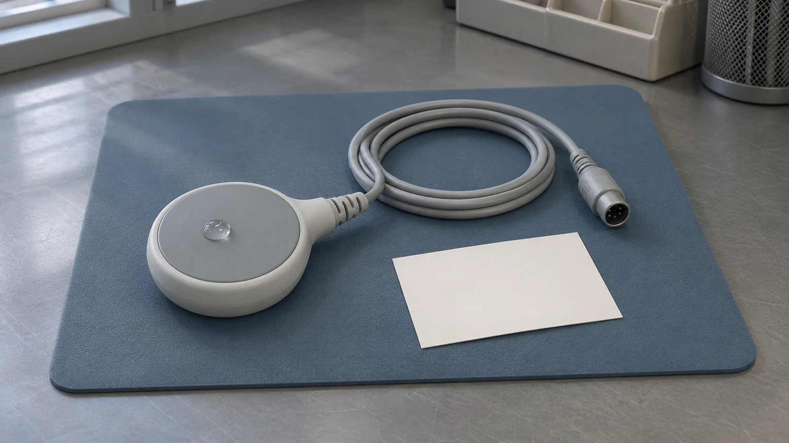
A bench pass can leave the transducer unchecked
An electrical ultrasound simulation cable replaces the fetal ultrasound transducer at the monitor input. A passing result therefore supports the connected monitor path at the settings and outputs actually checked; it leaves the removed transducer and its cable untested. A mechanical fetal-heart probe, such as the Fluke MFH-1, supplies a physical stimulus at the transducer face so that the transducer participates in the test. Neither result establishes clinical fetal heart rate accuracy.
Consider a hypothetical service handover: the console responds normally to an electrical simulator, but staff still report an intermittent trace with the assigned ultrasound transducer. Both observations can be valid. The first question is whether that individual transducer was included in the bench setup. The electrical pass alone neither clears the transducer nor identifies the cause of the complaint.
Four measurement paths, with different test boundaries
External Doppler monitoring derives fetal heart rate (FHR) from ultrasound reflected by moving fetal cardiac structures. Direct fetal ECG (DECG) acquires an electrical cardiac signal instead. Maternal ECG (MECG) measures maternal heart rate. Uterine activity is another measurement, obtained externally with TOCO or internally with an intrauterine pressure (IUP) system. A console may support some or all of these functions; inventory the installed configuration before selecting tests.
The PS320 datasheet lists separate ultrasound, fetal ECG, maternal ECG and uterine-activity simulation functions. Its mechanical accessory adds a physical interface to the ultrasound transducer. A shared simulator enclosure does not make these interchangeable tests.
The FDA device definitions in 21 CFR Part 884 Subpart C also distinguish fetal ultrasonic monitors (§884.2660), obstetric ultrasonic transducers (§884.2960), fetal scalp spiral electrodes (§884.2675), IUP monitors (§884.2700) and external uterine contraction monitors (§884.2720). These definitions describe device types; they do not prescribe a service test or establish that one channel test covers another.
A coverage matrix for reviewing the service result
Use this matrix to compare the recorded connection point with the proposed release claim. Coverage depends on which accessories were physically included and which observations were made. It is a documentation aid, not a substitute for the monitor service procedure. The interface distinctions come from the PS320 manual and Fluke application note.
| Channel and interface | Evidence the setup can support | What remains outside that result | What to identify in the record |
|---|---|---|---|
| Ultrasound input: electrical simulation cable | Monitor response to the compatible electrical stimulus at the tested settings. | The removed ultrasound transducer, its cable and physical acoustic coupling; unobserved outputs. | Monitor channel, simulation cable, settings and the outputs actually assessed. |
| Ultrasound: mechanical probe at the transducer face | Response with the identified transducer and its connected cable included in the path. | Clinical signal acquisition, patient conditions and any transducer checks outside the procedure. | Transducer identity, coupling method, required coverage and observed response. |
| DECG: compatible electrical test interface | Response of the connected DECG path under the specified bench setup. | Ultrasound acquisition and electrode contact during patient use; any omitted accessory. | DECG adapter, patient cable or module included, stimulus and observed response. |
| Maternal ECG: compatible simulator connection | Maternal ECG response through the lead set or adapter actually connected. | Fetal ultrasound performance; cross-channel verification unless separately assessed. | Maternal input, included lead set and any separately documented coincidence assessment. |
| External uterine activity: electrical TOCO simulation or actual transducer check | An electrical cable checks the connected monitor path; a physical transducer check includes the sensor. | The physical TOCO sensor when replaced by a cable, and the IUP path. | Whether the actual TOCO transducer was included or replaced, plus observations. |
| IUP: compatible electrical simulation or documented pressure test | Response through the components included in that particular setup. | External TOCO; clinical catheter conditions and components omitted from the bench arrangement. | Electrical or pressure interface, included components, settings, units and readings. |
Write observations separately from conclusions. A displayed rate is an observation; acceptance requires comparison with the applicable criterion. A blank cell should become an explicit status such as not tested, not fitted, failed or pending clarification. Do not silently turn missing evidence into a pass.
What the electrical ultrasound cable can establish
The PS320 manual calls its accessory an ultrasound (fetal ECG) simulation cable. The name is not evidence that a DECG test was performed. Identify the monitor input used and the documented purpose of the compatible cable. The cited manufacturer documentation does not provide enough circuit detail to claim that every such cable verifies the complete Doppler demodulator or every internal component.
Fluke’s application note supports changing simulated rates to assess monitor response and alarms for the listed monitor families. Alarm behavior counts only when it is deliberately exercised and observed. A steady rate display does not automatically verify signal-loss handling, recorder registration, central-station transmission or an alarm delay. Add each required output as a separate result.
If the test fails, first review compatibility, selected mode, setup and test-equipment condition under the applicable instructions. Failure does not identify a defective board by itself. If it passes, retain the result with its limited scope; it can be useful when comparing later tests that include the actual transducer. For broader alarm evidence, see patient monitor alarm verification after service.
What changes when the transducer is included
The PS320 Users Manual, printed page 13, describes gel coupling between the transducer face and MFH-1 simulation window, with the window used over each transducer crystal in turn. It also states that the MFH-1 requires the specified battery eliminator rather than simulator battery power alone. These are conditions of that accessory’s documented method, not instructions to improvise another fixture.
A record should distinguish a general response from completion of the required coverage. If the applicable method calls for individual crystal checks, a response at one position cannot stand in for all positions. Record the actual transducer and cable, the method used and the observations. Do not infer an acoustic output measurement, complete transducer characterization or a specific internal failure from an audible response alone.
Commercial availability is also separate from test validity. Fluke’s PS320 product and kit listings include the MFH-1 and model-specific interface cables. The selected kit still needs to match the monitor. The 2020 Sensors prototype paper illustrates mechanical stimulation but is neither a universal service procedure nor a reason to build a substitute for a documented compatible test fixture. Its suggestion that hardware mechanical simulators were unavailable should not be treated as a current market fact.
Keep the other channels and outputs explicit
The Fluke application note describes DECG and maternal ECG as separate tests using their own interfaces. Document the patient module, adapter and cable actually included. A generic rate response does not establish every amplifier characteristic or lead-fault function. Likewise, an electrical uterine-activity cable can replace a physical TOCO transducer; a good trace from that cable leaves the replaced sensor untested.
For multiple-fetus configurations, record each required ultrasound channel and the mapping between transducers, displayed labels and traces. Simulator US1/US2 outputs should not be assumed to correspond universally to fixed monitor sockets or labels. Identify the applicable model behavior. Keep trace identification, recorder output and any cross-channel verification assessment as separate observations.
For every output named in the work order, ask whether someone observed it at its destination. A local display result cannot be copied into a remote-output field. If a destination was unavailable, record that limitation and the follow-up owner rather than extending the scope of the local test.
A clean simulated trace has clinical limits
The cited Philips Avalon Instructions for Use is Release F.0, part M2703-9001D, printed December 2007. It warns about maternal heart rate being mistaken for fetal heart rate, artificial traces from regular mechanical or electromagnetic influences, and rare half- or double-counting. It describes cross-channel verification as an aid when rates coincide. It does not justify assuming a universal audible coincidence alarm or a bench test that guarantees clinical discrimination.
Those cautions explain why an orderly bench trace is insufficient evidence of a valid fetal signal on a patient. A functional test evaluates the documented setup and conditions. Clinical source identification and interpretation belong to the clinical team. Use the current instructions for the installed model and software; the historical IFU is used here for its published cautions, not as a current acceptance procedure.
If the complaint remains unresolved despite passing checks, preserve both findings: the bench result and the reported clinical behavior. Describe what could and could not be reproduced. Do not erase the discrepancy by declaring the device accurate, or attribute it to positioning or staff technique without investigation.
Use standards scope without inventing service limits
IEC’s public description of IEC 60601-2-37:2024 concerns basic safety and essential performance of ultrasonic diagnostic and monitoring equipment. The public scope of IEC 60601-2-27:2011 explicitly excludes fetal heart rate monitoring. A standards citation in a paper or a multifunction monitor’s documentation does not make that ECG standard a Doppler FHR service protocol.
The Sensors paper cites IEC 60601-2-27 and reports prototype test results. Keep that research context separate from service acceptance. Do not transfer its percentage figure, the simulator’s own specification or another monitor’s rate points into a universal pass criterion. Obtain the applicable monitor procedure and revision, required test capability and acceptance limits through the organization’s controlled maintenance process. If those criteria are unavailable, the record should say acceptance is pending.
Build a record that preserves the test boundary
Current 42 CFR 482.41(d)(2) requires hospital facilities, supplies and equipment to be maintained for an acceptable level of safety and quality. CMS’s December 2013 S&C: 14-07-Hospital memo discussed maintenance documentation and inspection and testing after major repairs or upgrades. Treat that dated memo as background, not a current fetal-monitor test protocol. Neither source supplies the field list below or a universal simulator requirement.
The following is a recommended review template. It adds interface detail to the general medical equipment service record so that another technician can understand what the result covers. Retain the original observations when adding later clarification; do not reconstruct missing settings from today’s bench setup.
| Record field | Recommended entry | Decision it supports |
|---|---|---|
| System identity and complaint | Console model, serial or asset ID, installed configuration, service event and the reported symptom. | Whether the test addressed the equipment and configuration involved in the handover. |
| Included accessories | Individual transducer, cable, module and adapter identities where available; identify any substituted shop accessory. | Whether evidence belongs to the assigned assembly or only to the shop configuration. |
| Interface and coverage | Electrical injection or physical stimulus, connection point, channel and required sensor coverage completed. | Which part of the acquisition chain participated, and which part was bypassed. |
| Test-equipment condition | Simulator identity, applicable firmware, cable identity and calibration or verification status at the time of use. | Whether the stimulus and method can be traced. See the linked provenance guide for version records. |
| Settings and observations | Actual selected settings, units, readings and observed behavior; attach relevant test output. | What happened during this run, independently of the final pass/fail interpretation. |
| Acceptance reference | Controlled monitor procedure and revision, relevant section, criteria and comparison outcome. | Why the observations were accepted, rejected or left pending. |
| Separate functions and exclusions | Applicable alarms, audio, recorder, remote output and other channel results; state not tested or not fitted where appropriate. | Whether the proposed release claim extends beyond the completed checks. |
| Disposition and ownership | Remaining gaps, next action and owner, technician identity, and the authorized release decision under local policy. | Who must resolve an incomplete result before it is relied upon. |
For firmware and preset details, use simulator result provenance. Record the status that applied when the test ran. A calibration due date alone cannot describe the entire setup, and the presence of a calibration certificate does not establish monitor acceptance.
For a completed mechanical test, describe the individual transducer, included cable, applicable method, coverage and observations. Link that result to the earlier electrical test without merging their scopes. If an accessory was changed between runs, explain the change. A comparison is useful only when a reviewer can tell what stayed in the setup and what was substituted.
Resolve gaps before making the release decision
Reconcile the complaint with the test map. Confirm whether the assigned transducer was included, and whether every function required by the applicable procedure has a result.
Keep damage, failed checks and uncertain compatibility visible. Escalate to qualified service using the current model documentation; do not infer an internal board or crystal fault from a single failed response.
Keep functional evidence and electrical safety evidence separate. Apply the relevant model procedure and institutional maintenance policy; the simulator pass does not establish electrical safety.
Refer unresolved clinical signal concerns to the clinical team and equipment performance concerns to the appropriate service owner. Record the disposition and remaining restrictions before release.
The useful handover is a set of bounded findings: this console path was checked, this transducer was included or excluded, these outputs were observed, and these questions remain open. That gives the receiving team evidence it can act on without turning a simulator result into a claim it cannot support.