
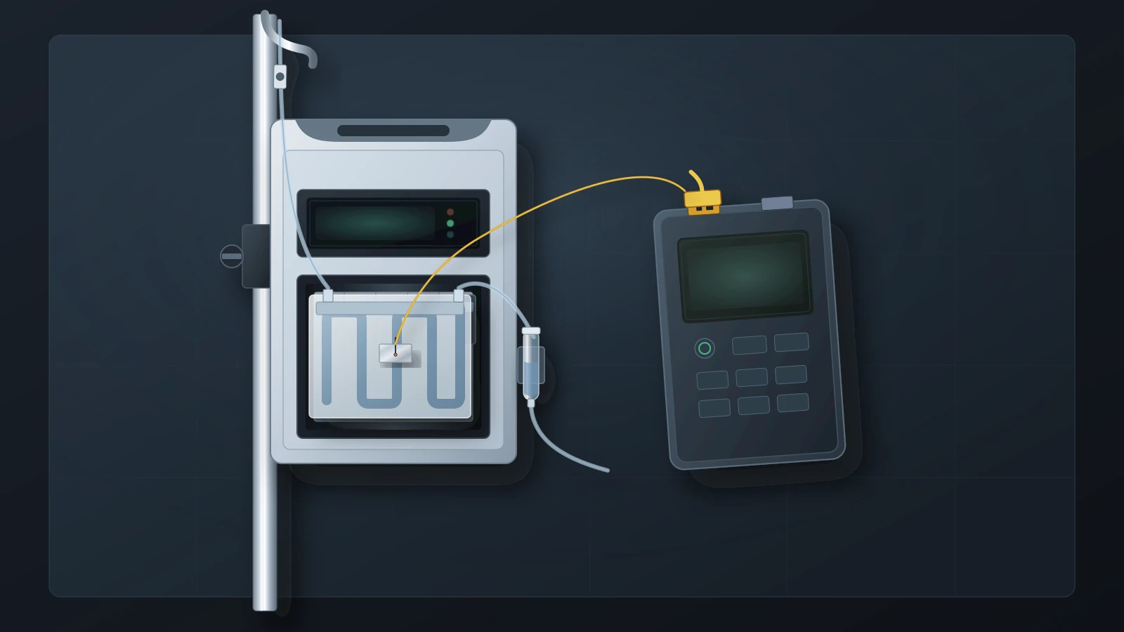
What a fluid warmer display actually measures
A fluid warmer comes back from service, or a nurse charts one during a case, and the front panel reads 41°C. Is that the temperature of the fluid reaching the patient? It depends on the model. Of the five named models reviewed here, only one is documented as displaying fluid temperature. The others report a heater plate, a recirculating bath or a heating profile. In each case the warmer is reporting its own condition, not the infusate at the patient.
The models reviewed here fall into four measurement boundaries, and each boundary answers a different question:
Heater plate. On the 3M Ranger Model 245 and Model 247 the alphanumeric display indicates the heater temperature during normal operation, and the alerts are stated in heater-temperature terms. A disposable cassette sits between the plates and the fluid.
Recirculating bath. For the ICU Medical Hotline, Manitoba's transfusion guide tells staff to wait for the recirculating solution temperature display to reach 41°C. The circulating solution warms the IV line through the set; the display is not a probe in the infusate.
Heating profile. On the ASTOFLO PLUS ECO, a standard infusion line is inserted into the groove of a heated profile, and the instructions state that the displayed profile temperature is not equal to the temperature of the medium being warmed.
Fluid path. On the Stryker/Gaymar Medi-Temp III FW601 the display shows the actual fluid temperature or the setpoint, and the manufacturer's verification measures output fluid at the bubble trap under defined flow and room conditions.
The regulations don't settle this for you. Under 21 CFR 864.9205, a blood or plasma warmer that does not use electromagnetic radiation is a Class II (performance standards) device. For hospitals, 42 CFR 482.41 requires facilities, supplies and equipment to be maintained to ensure an acceptable level of safety and quality. CMS interpretive guidance for Tag A-0724, revised by S&C 14-07, adds that all equipment must be inspected and tested for performance and safety before initial use and after major repairs or upgrades. None of these documents says what a particular warmer's display measures. Only the model documentation does, so that is where the verification method has to come from.
What the 3M Ranger 245 and 247 measure, and what their OEM checks verify
The Ranger Model 245 warms blood, blood products and IV fluids. The Model 247 warms irrigation fluids. Both use heated plates and a disposable cassette. The Ranger Model 245/247 service manual says the alphanumeric display indicates the heater temperature during normal operation. In an over-temperature condition it alternately flashes a temperature (43°C or higher on the 245, 48°C or higher on the 247) and the word HI. In an under-temperature condition it flashes 33°C or lower and the word LO. The Model 245 operator's manual describes the alerts the same way: the heater temperature rose to 43°C, or the heater temperature has fallen to 33°C. The Model 247 operator's manual describes its display the same way, as indicating the heater temperature during normal operation. Neither manual describes the display as a measurement of fluid leaving the cassette or the patient line.
The manufacturer's preventive-maintenance check works at the same boundary. Summarized rather than reproduced: a fine thermocouple is taped with aluminum tape to the top surface of the warming cassette. The cassette is primed with room-temperature saline or water, the patient line is clamped so nothing flows, and the unit warms up for five minutes. The display should then read 41°C ±1, and the reading on a calibrated thermocouple temperature monitor is noted. If the reading is not 41°C ±1, the manual says to call 3M technical support. The Model 247 uses the same check with its irrigation cassette. The maintenance logs say operating temperature and alerts should be tested at least every six months or according to institutional protocol.
Be clear about what that check proves. It shows that the display and an independent sensor on the cassette surface agree at zero flow. It does not measure fluid at a clinical flow rate, and the manufacturer does not claim it does. The same manual notes that most handheld temperature meters have a ±1°C tolerance, which is as wide as the acceptance band itself.
The service manual's alert-point test checks the Model 245 audible alert at 43°C (±1). It then checks a secondary set point of 46°C (+3, −2), at which the unit cuts power to the heaters. On the Model 247 the corresponding points are 48°C (±2) and 50°C (±2). The secondary alert is designed to latch and keep alerting through a momentary power cycle. After the test, the manual says the unit is ready to return to service once it cools to normal operating temperature, approximately 20 to 30 minutes. The test puts the unit into an over-temperature test mode and the manual calls it technique-sensitive, so it belongs in the OEM procedure, not in a summary like this one.
Adjustment is not an option. The service manual states that temperature adjustments cannot be made to the Ranger warming unit, and that all repair, calibration and servicing must be performed by 3M or an authorized service technician. Both operator's manuals state that there are no user-serviceable parts. A display reading Er 4 or Open indicates an open wire on the temperature sensor. The instruction for that is not to use the unit and to call 3M.
Water-bath warmers: the Hotline display shows the recirculating solution
ICU Medical's Hotline product page says the system keeps blood and fluids warm between 37 and 42°C, delivering up to 5,000 mL/hr under gravity flow. It also says the triple-lumen tube eliminates patient line cool down and that maintenance is scheduled with each use, every 30 days and every 12 months. Those are product claims, not test results. The bench data later in this article show what an added extension line can do.
What the Hotline display shows is clear from how clinical guidance uses it. The Shared Health Manitoba Transfusion Best Practice Resource Manual 2024 quick guide for blood warmers tells staff to wait until the recirculating solution temperature display reaches 41°C before adjusting the IV flow. It also says an over-temperature warning signal means warming has stopped and immediate operator intervention is required. So the number is the temperature of the circulating solution that warms the line. Numeric Hotline alarm points are not given in the documents reviewed for this article. Take them from the operator's manual for your model, not from another warmer's values.
The same Manitoba resource sets out principles that show how display readings end up in clinical records. Warming devices should have a temperature sensing device and a warning system. They must be validated by Biomedical Engineering, with maintenance and alarm testing performed to manufacturer recommendations. During warmed-fluid administration, the display temperature should be documented initially and at least hourly. This is a Canadian regional resource, not a US requirement, but the practice is common. A charted display value is a defensible record of device state. It is not a record of infusate temperature at the patient, and biomedical teams can help clinical documentation say so.
For maintenance, ICU Medical's fluid warmer maintenance sheet (C24-6924) covers the Level 1 H-1200, the Hotline and the Normoflo, all of which use recirculating solution. The reservoir is disinfected and the solution changed every 30 days if distilled water or 35% isopropyl alcohol is used (the alcohol option is for the Hotline only), or every 12 months with 0.3% hydrogen peroxide. The 12-month checklist includes an alarm signal test, an add recirculating solution test, a check disposables test, an over temperature alarm test, verify temperature calibration, and electrical safety tests. The sheet says only competent personnel should perform routine maintenance and points to the operator's manuals for the full procedures. It names the tests but does not give acceptance values, so a work order that says only “annual PM done” cannot show which bath temperature was verified, or against what.
Two designs that state their own limits: FW601 and ASTOFLO PLUS ECO
These two manuals take opposite positions on fluid temperature, and both are explicit about it. Most warmer documentation is less clear.
The Medi-Temp III FW601 operator's and service manual says the LED display shows the actual fluid temperature or the setpoint, which is user-selectable from 38.0°C to 41.0°C in 1.0°C steps. Its LO control alarm sounds when the unit senses a fluid temperature below 34.0°C. A backup system, independent of the main controller, monitors fluid temperature continuously and interrupts heater power if output fluid exceeds 45.0°C. If the backup system finds a main-controller failure, the remove-from-use (RFU) indicator lights and the device shuts down.
Section 6.2 of the FW601 manual, Output Fluid Temperature Verification, is a fluid-path test. It is done every twelve months or as the facility's preventive maintenance program specifies. The unit is factory calibrated at 100 mL/min. Room temperature must be 20°C to 24°C, and a Gaymar FWT1 temperature sensor is attached to the output of the bubble trap. The manual also allows an alternate in-trap sensor method. Room-temperature water flows at 100 mL/min with the setpoint at 41.0°C for 10 minutes. The output must then be 41.0°C ±1.1, or 1103 to 1204 ohms with the FWT1 and an ohmmeter. If the result is out of range, check the setup and repeat. If it is still out of range, contact the dealer for service; the device cannot be field adjusted.
Even this check has a boundary. It proves output temperature at one flow rate and one room-temperature band. The manual says fluid temperatures exiting the patient line are affected by flow rate. Its typical flow-versus-temperature curve, measured at the end of the patient line with extension sets, is a characterization rather than a field test.
The ASTOFLO PLUS ECO works differently. A standard infusion set is inserted into the groove of a flexible heating profile. Its instructions for use, issued by Stihler Electronic and published on Gentherm's website, say plainly that the display shows the profile, not the fluid:
“During operation, the control panel shows the internal temperature of the heating profile; this is not equal to the temperature of the medium to be warmed. The ASTOFLO PLUS ECO neither regulates nor monitors the current temperature of the medium to be warmed.”
— ASTOFLO PLUS ECO Instructions for Use
The instructions list what changes the fluid temperature: room temperature and ventilation, inlet temperature, flow rate, and the infusion-set material. The alarms are tied to the profile. A low-temperature alarm triggers when the profile stays at or below the set temperature minus 3°C for longer than 10 minutes. An excessive-temperature alarm has a limit of 43.6°C ±0.5, backed by two independent excessive-temperature cutoffs. There is also a cable-break alarm.
The recurrent test, required at least every 12 months, is consistent with that design. It covers visual inspection, protective earth and leakage measurements, manual tests of the excessive-temperature and cable-break cutoffs, and a heating-up test. In the sensor test, the cooled profile's two temperature sensors are compared with a room thermometer, and all three readings must agree within 1.2°C. No outlet-fluid measurement is involved. A technician who compares outlet fluid with the ASTOFLO display and calls the difference a calibration error has misread the design. The instructions also say repairs may only be carried out by persons authorized and qualified by the manufacturer.
The named-model evidence map: plate, fluid, display and alarms
The map below draws only on the manufacturer documents cited above. Every value is specific to its model, and for the Ranger to its document and unit revision. None is a test limit for any other warmer. Use it to see which boundary each check covers before you write the work order, not as a substitute for the current OEM procedure.
| Model and design | What the display reports | OEM verification and its conditions | Alarm and cutoff boundaries | Adjustment and escalation |
|---|---|---|---|---|
| 3M Ranger Model 245 (dry heat, blood/IV fluid) | Heater temperature during normal operation | Thermocouple taped to cassette top surface; room-temperature prime; patient line clamped (no flow); 5-minute warm-up; display 41°C ±1 and calibrated monitor reading noted; at least every 6 months or per institutional protocol | LO 33°C; HI 43°C (±1); heater-power cutoff 46°C (+3, −2) in the service manual; 44°C (Rev N and newer) or 46°C (Rev A to M) in the operator's manual | No temperature adjustment; out of specification: call 3M; Er 4 or Open: do not use |
| 3M Ranger Model 247 (dry heat, irrigation) | Heater temperature during normal operation | Same cassette-surface check with the irrigation set; display 41°C ±1; at least every 6 months or per institutional protocol | LO 33°C; HI 48°C (±2); heater-power cutoff 50°C (±2) | No temperature adjustment; no user-serviceable parts; Er 4 or Open: do not use |
| ICU Medical Hotline (recirculating solution) | Recirculating solution temperature | Every 12 months: verify temperature calibration, over temperature alarm test, alarm signal, add-solution and check-disposables tests, electrical safety tests, per the operator's manual; solution change every 30 days or 12 months by solution type | Over-temperature warning stops warming; numeric points not given in the documents reviewed (take them from the model's operator's manual) | Competent personnel only; acceptance values are in the operator's manual |
| Stryker/Gaymar Medi-Temp III FW601 (dry heat, fluid sensing) | Actual fluid temperature or the setpoint | FWT1 sensor at the bubble-trap output; room 20–24°C; room-temperature water at 100 mL/min; setpoint 41.0°C; 10 minutes; output 41.0°C ±1.1 (1103–1204 ohms); every 12 months or per PM program | LO below 34.0°C sensed fluid; HI above 43°C (transient); backup interrupts heater power above 45.0°C output fluid | Factory calibrated, not field adjustable; still out of range after re-test: dealer service |
| ASTOFLO PLUS ECO (heating profile) | Internal heating-profile temperature, stated as not equal to the fluid | At least every 12 months: profile sensors versus room thermometer within 1.2°C; heating-up test; manual cutoff and cable-break tests; electrical safety | Low: at or below set temperature minus 3°C for more than 10 minutes; excessive: 43.6°C ±0.5; two independent cutoffs | Repairs only by persons authorized by the manufacturer |
Why flow rate and tubing change the temperature after the warmer
The displays in the map cannot show what happens downstream. Two peer-reviewed bench studies measured it. Kim et al. (2021) tested a Hotline HL-90 set to 40°C and a Barkey S-line maintained at 39.5°C, using saline in a recovery-unit room kept at 23°C. They measured at the warmer outlet and at the end of a 90 cm non-insulated extension set. Fluid started at room temperature (21–23°C), cold (9–11°C) or warm, and ran at 100 or 250 mL/h.
Low flow, room-temperature fluid: at 100 mL/h the outlet medians were 40.3°C (Hotline) and 38.7°C (S-line). At the end of the extension they were 23.5°C and 24.5°C, median drops of 14.7°C and 15.1°C.
Low flow, cold fluid: the median drops were 16.3°C and 13.9°C. The authors wrote that the extension line reversed most of the warming, and that distal temperatures at 100 mL/h were similar to the room temperature.
Moderate flow: at 250 mL/h with room-temperature fluid the extension-line loss was small (median 1.1°C and 0.4°C), but the outlet temperatures differed by design: 38.7°C for the Hotline against 28.2°C for the S-line, a median difference of 10.5°C. The authors attribute the gap to the heating mechanism, a coaxial circulating water bath against a dry heating profile.
Thongsukh et al. (2018) tested a 1.5 m Barkey autocontrol 3XPT heater line set at 42°C, in an operating room near 24°C, with saline starting near 25°C. Outlet temperature was measured at the end of the heater line with an insulated thermistor. Mean outlet temperatures were 35.9, 36.3, 35.2, 34.2 and 33.0°C at 100, 300, 600, 900 and 1,200 mL/h, and the maximum single reading was 36.9°C at 300 mL/h. Warming efficacy was inversely associated with flow rate, and the outlet stayed below the 42°C setting at every rate tested.
In both studies the gap was under-warming, not overheating. A plate, bath or profile check at 41°C confirms that the heat source works. It cannot show what reaches the end of an uninsulated extension at low flow, or what leaves the outlet at high flow. These were single-device bench studies under fixed conditions. Treat them as evidence that the gap exists, not as pass or fail limits for your fleet. Line configuration and flow rate are clinical decisions. The HTM job is to make sure the record says which boundary was verified, so nobody mistakes a heater check for a delivered-temperature check.
The 2025 Ranger correction: a label that did not say where temperature was measured
The FDA's Ranger correction notice shows what happens when a label does not say where temperature is measured. The recall updates instructions and does not remove devices, but FDA identified it as the most serious type of recall. The affected products are Ranger high flow sets 24355 and 24370 used with the Model 245, and irrigation set 24750 used with the Model 247, all lots with a manufacturing date after March 2022. On April 21, 3M sent affected customers an Urgent Medical Device Correction first notice. The stated reason:
“The current label does not specify the location of the temperature measurement and corresponding flow rate based on inlet temperature.”
— U.S. Food and Drug Administration, Ranger Blood/Fluid Warming System correction notice
The system was labeled to deliver fluids at 500 mL/min while maintaining 33–41°C output. FDA's notice says testing showed the heater cannot adequately warm fluid at high flow rates. The confirmed limits are up to 333 mL/min with 20°C inlet fluid and up to 167 mL/min with 4°C inlet fluid. Outside those rates the device may deliver fluid at a lower temperature, and the potential consequences listed include hypothermia and death. No injuries or deaths had been reported. For the Model 247 with set 24750, the updated information is 20°C inlet fluid warmed to 33–41°C at gravity-fed flow rates up to 580 mL/min.
Solventum's revised flow-rate flyer for the high flow sets says fluids are warmed from 4–20°C inlet temperature to 33–41°C, with the over-temperature alert at 43°C and the under-temperature alert at 33°C. It lists set capacities of KVO to 100 mL/min for the pediatric set and KVO to 150 mL/min for the standard set. For the high flow set it gives KVO to 167 mL/min at 4°C inlet and KVO to 333 mL/min at 20°C. It also notes that the Ranger does not govern or regulate flow. The Ranger service manual cited above still carries the older KVO-to-500 mL/min description, so check the date on any Ranger document in your files.
Return to service: what the record should say
The current eCFR places the maintenance duty in 42 CFR 482.41(d)(2); the 2013 S&C 14-07 letter cites it as 482.41(c)(2) under Tag A-0724. That guidance lets a hospital adjust maintenance activities and frequencies from the manufacturer's recommendations under a documented Alternate Equipment Management program, based on a risk assessment by qualified personnel, with listed exceptions. It keeps the expectation that equipment is inspected and tested for performance and safety after major repairs or upgrades. When hospitals evaluate an AEM program, they are expected to address how equipment is checked for degradation that may not be readily apparent to staff, such as miscalibration. A warmer display cannot reveal its own miscalibration, which is the kind of degradation that guidance describes. Whether a particular warmer repair is major is a local decision; the major-repair return-to-service guide covers how to make and document it.
An entry such as “PM done, temp 41°C, pass” does not say whether 41°C came from the front display, a thermocouple on a cassette or a sensor in the outlet fluid, or at what flow. A surveyor or incident reviewer cannot tell a heater check from a delivered-temperature check. Building on the general service record elements, a warmer verification entry is most useful when it records:
Boundary measured: heater plate or cassette surface, recirculating solution, heating profile or outlet fluid, and whether the value is the display or an external reference.
Method and document: the OEM procedure applied, its document number and revision, and the unit revision where limits differ by revision.
Conditions: flow (including “no flow, line clamped”), room temperature, test medium and dwell time, as the procedure specifies.
Reference instrument: identifier and calibration status, checked the way the calibration certificate guide describes.
Results against the OEM window: display reading, reference reading and acceptance window, as found and, after any service, as left.
Alarm, cutoff and safety checks: the alarm and cutoff tests the OEM procedure calls for, plus electrical safety testing under your program.
Disposition: returned to service, or removed and escalated, with the reason.
This is a documentation pattern, not a regulatory checklist. It mirrors what the OEM documents already do. The Bair Paws Model 875 service manual covers a forced-air warming unit from the same manufacturer family, not a fluid warmer. It requires a safety inspection after repairs and before return to service, including calibration of operating temperature and a test of the over-temperature detection function. Calibration uses a Model 90055 Temperature Test Kit that simulates the gown, read with a calibrated thermometer that accepts a K-type thermocouple, to a 43.0°C ±0.5 steady state. Calibration and the over-temperature test recur every six months, and the over-temperature threshold cannot be adjusted. The manufacturer defines where the reference reading is taken, and the record should say where that was.
Safe escalation boundaries: what not to touch and when to stop
For the fluid warmers reviewed here, field temperature adjustment is not an option for the hospital technician. The Ranger service manual says temperature adjustments cannot be made. The FW601 is factory calibrated and cannot be field adjusted. ASTOFLO PLUS ECO repairs may only be carried out by persons the manufacturer has authorized and qualified. The Ranger and FW601 manuals both state there are no user-serviceable parts. Even the Bair Paws forced-air unit, whose service manual does include an operating-temperature calibration, states that its over-temperature threshold cannot be adjusted.
Check the reference instrument too. The Ranger manual's note that most handheld temperature meters have a ±1°C tolerance means a typical handheld meter's uncertainty is as wide as the ±1°C acceptance band. The FW601 manual specifies its references: the FWT1 sensor with an ohmmeter of 1.5% accuracy and no more than 100 µA excitation current, or a waterproof sensor and meter accurate to ±0.3% across 30–60°C with a thermal time constant of 2 seconds or faster. Use the instrument the manufacturer specifies. If a reading falls at the edge of the window, repeat the check or escalate rather than recording a marginal pass.
Each manual names conditions for taking a unit out of use:
Ranger sensor fault: the display reads Er 4 or Open, an open wire on the temperature sensor. Do not use the unit; call 3M.
Ranger check out of specification: the cassette-surface check is not 41°C ±1. Call 3M technical support; the unit cannot be adjusted.
Ranger backup activation: the independent backup safety alert has activated, or the unit alerts while switched off. Unplug it and call 3M.
FW601 failures: the output check is still out of range after the setup is checked and the test repeated, or the display shows FA_, or the RFU light is lit. Remove from use and request service.
ASTOFLO PLUS ECO conditions: damaged cables, housing or heating profile, liquid exposure, or an alarm without a known cause. Do not use it until the condition is remedied. If the alarm LED and tone do not activate at switch-on, remove the device from service immediately.
Open corrections: an affected unit or set without the updated instructions goes through the recall workflow before you call it ready.
None of this means the display can't be trusted. It means every reading needs a label. A 41°C reading on a Ranger, a Hotline, an ASTOFLO PLUS ECO and an FW601 records four different things: a heater plate, a circulating bath, a heating profile and outlet fluid. Write down which one you measured, how, and under what conditions, and the record will support the return-to-service decision.