
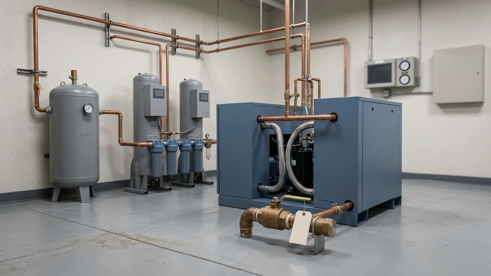
Take a scenario that clinical engineering teams will recognize. A contractor services the hospital's medical-air compressor package overnight and closes the ticket after a clean run test. The next morning the master alarm panel shows a medical air dew-point alarm, and respiratory therapy finds moisture in the supply lines of two ICU ventilators. Biomed is paged first, because the symptom is on a device. Facilities points to the passed checkout. Nobody has a written answer to three questions: who owns the dryers and the monitors, what evidence each side needs, and what actually closes the event.
The workable default has three parts. The plant—intake, compressors, receiver, dryers, filters, regulators and the source valve—belongs to facilities or a qualified medical-gas contractor, together with the distribution piping. The devices that connect at the outlet belong to clinical engineering. The items that sit between those worlds—the dew-point and CO monitors, the master and area alarm panels, the zone valves and the outlets—each need one named owner of record, because those are the items that fall between departments. And the event is closed by monitor and verification evidence, not by a passed compressor checkout.
The boundary the code already draws: intake to source valve
NFPA 99 defines a central supply system as the equipment needed to produce, condition, control and monitor the gas, including all equipment from the atmospheric intake on air compressors through to the source valve, according to an ASPE summary of the 2018 edition. For medical air, that scope covers the intake pipe and screen, the compressor modules and aftercoolers, the receiver, the dryers, the filters and final line regulators, and the source valve itself. A 1996 APSF review of medical-air plants places the source shutoff valve downstream of the final line regulators, positioned so the entire source of supply can be isolated from the piping system.
The quality monitors sit inside that boundary. NFPA's current-cycle committee text places medical air quality monitoring downstream of the medical air regulators and upstream of the piping system, and puts the valved sample port downstream of the dew-point and CO monitors but upstream of the source shutoff valve. The dew-point and CO transmitters are therefore plant components even though their alarms report to panels in clinical areas—one reason they are so easy to orphan.
Everything downstream of the source valve is distribution: the main line, risers, zone valves, area alarms and station outlets. It is still part of a Category 1 piped gas system under NFPA 99, but its components and failure modes differ from the plant's, and the critical components Joint Commission lists for it—master signal panels, area alarms, automatic pressure switches, shutoff valves, flexible connectors and outlets—are not compressor parts.
What medical air may feed is narrow. In the 2024 edition, medical air sources are connected only to the medical air distribution system and used only for human respiration, calibration of medical devices for respiratory application, and simulation centers. Powering surgical tools is the job of the medical support gases, nitrogen or instrument air. The ASPE summary lists medical-air usage among the requirements that cannot be grandfathered, and APSF quotes NFPA's reasoning that using a medical air compressor for other purposes increases service interruptions, shortens service life and adds opportunities for contamination.
Instrument air is a separate system with its own numbers. The ASPE deck gives its standard pressure as 160–185 psig, against 50–55 psi for medical air, and NFPA's current-cycle alarm text sets the instrument air dew-point alarm at −30 °C (−22 °F) versus +2 °C (+35 °F) for medical air. A mechanical room that houses both holds two systems, each with its own records.
Clinical engineering's side begins at the outlet. Supply hoses, flowmeters, blenders, ventilators and anesthesia machines are medical equipment on the HTM inventory. A 2019 NEHES presentation on medical-gas management flags flowmeters and suction regulators used with the piped systems as an inventory whose owner is often unclear ("biomed?"), which is exactly the kind of boundary row the matrix below exists to settle. The same split between a device's own checks and the facility supply behind the wall appears in our article on anesthesia workstation checkout versus HTM maintenance.
Which rule owns which side: CMS, NFPA 99, and Joint Commission
For hospitals in Medicare and Medicaid, 42 CFR 482.41(c) requires the hospital to meet the applicable provisions of, and proceed in accordance with, the Health Care Facilities Code—NFPA 99 with TIAs 12-2 through 12-6—and 482.41(e) identifies the edition as 2012. Under 482.41(c)(1), chapters 7, 8, 12 and 13 of the code do not apply to hospitals; Chapter 5, which covers gas and vacuum systems, does. Separately, 482.41(d)(2) requires facilities, supplies and equipment to be maintained to ensure an acceptable level of safety and quality, and 482.41(a)(2) requires facilities for emergency gas and water supply.
NFPA 99 puts piped medical gas systems in Category 1, the highest risk category; HFM describes it as the level with a high likelihood of severe injury. The operation and management requirements quoted in the NEHES presentation say health care facilities shall develop and document periodic maintenance programs for these systems and their subcomponents, and that inventories include at least all source subsystems, control valves, alarms, manufactured assemblies containing patient gases, and outlets.
Joint Commission manages the system under its Environment of Care utility standards, not its medical equipment standards:
EC.02.05.01 requires a written inventory of utility-system operating components that includes all life-support systems, written inspection and maintenance activities for the inventoried components, and written intervals. In the 2012 hospital text, those intervals rest on criteria such as manufacturers' recommendations, risk levels or hospital experience. The same standard requires written procedures for utility disruptions: shutting off the malfunctioning system and notifying staff in affected areas, performing emergency clinical interventions, and obtaining emergency repair services.
EC.02.05.09 requires the hospital, in time frames it defines, to inspect, test and maintain critical components of piped medical gas systems—master signal panels, area alarms, automatic pressure switches, shutoff valves, flexible connectors and outlets—and to document that work. It requires testing for purity, correct gas and proper pressure when the systems are installed, modified or repaired, and main supply and area shutoff valves that are accessible and clearly identify what they control. Joint Commission's 2025 survey-readiness tool shows no prescribed frequency for critical-component ITM, recommends a risk assessment if the frequency is less than annual, and ties the element to NFPA 99-2012 section 5.1.14.2.
EC.02.05.05, in the same tool, expects high-risk utility components on the inventory—including life-support equipment—to have completion dates and results documented, with a 100 percent completion rate for the required activities.
None of these texts names a department. What they require is an inventory that includes the plant, written activities and intervals, documented results, qualified people, and procedures for the day the system fails. That is why "facilities owns it" or "biomed owns it" is not a compliance answer. A matrix that names an owner for every row is.
Changing intervals follows the same logic as any alternative maintenance decision. The hospital may set ITM frequencies through its own policy and risk assessment, but it has to document why, and the 100 percent completion expectation then applies to whatever schedule it adopted. The decision discipline is the one described in our article on AEM versus manufacturer maintenance, applied here to a utility system rather than a medical device.
Medical air is also a drug. APSF notes that the United States Pharmacopeia treats medical air as a manufactured drug, and the NEHES presentation calls it the only regulated drug manufactured on site. FDA's medical-gas CGMP regulations took effect on December 18, 2025, and FDA's draft guidance on them is addressed to manufacturers of medical gases. How those rules apply to a particular hospital's on-site plant is a question for regulatory counsel and outside the scope of this article; the maintenance duties discussed here come from CMS, Joint Commission and NFPA 99.
The responsibility matrix: component, owner of record, and the evidence each side keeps
The matrix below proposes a default owner for each component and the record that owner keeps. The owner column is an editorial recommendation, not a code mandate: the code assigns duties to the equipment owner and the organization, and each hospital has to make and document its own assignment. What matters is that every row ends up with one name.
| Component | Default owner of record | Interface with the other side | Evidence the owner keeps |
|---|---|---|---|
| Intake pipe, screen and location | Facilities | Intake location is re-checked when docks, parking, helipads or HVAC work change nearby | Siting check against the adopted edition; screen and pipe condition; changes around the intake |
| Compressor modules, motors, belts, aftercoolers | Facilities or a contracted medical-gas service provider | Owner notifies clinical areas before work that reduces available air | Work orders against the installed model's manual; manufacturer-reserved tasks done by an authorized technician |
| Receiver, safety valve and drains | Facilities | None routinely | Condensate, auto-drain and safety-valve checks and drain rebuilds at the manual's intervals |
| Desiccant dryers, pre-filters, after-filters, purge mufflers | Facilities or contractor | Dryer faults are the usual origin of dew-point alarms | Dryer rotation, filter and muffler changes and desiccant replacement at the manual's intervals; filter-indicator status |
| Final line regulators and source valve | Facilities | Source valve position during service is controlled under the hospital's permit-to-work | Valve labeling and accessibility; valve position recorded on the work order |
| Dew-point and CO monitors | One named owner, usually the plant owner | Readings and alarm history go to clinical engineering after any supply-quality event | Calibration and sensor-accuracy records; transmitter replacement dates; recalibration after servicing |
| Master and area alarm panels | One named owner, usually facilities | Panels sit in clinical areas: clinical staff respond, the owner tests | Alarm-indicator test results in hospital-defined time frames |
| Distribution piping, risers, zone valves | Facilities, with licensed installers for piping work | Any cut-in or breach triggers verification of the affected portion | Permit-to-work; verification report; zone-valve labeling and accessibility checks |
| Station outlets | Facilities or an assigned ASSE 6040 maintainer | Clinical engineering reports outlet faults found during device work | Outlet ITM results in hospital-defined time frames |
| Hoses, flowmeters, blenders, ventilators, anesthesia machines | Clinical engineering | Device findings that point upstream go to the plant owner | Device inventory, PM and repair work orders; quarantine and return-to-service records |
The rows most likely to fall between departments are the monitors, alarm panels, valves and outlets, because each has a plant end and a clinical end. If a contractor services the compressor package, its scope should list monitor calibration, sensor replacement and alarm testing by name; a service ticket that does not mention them is not evidence that they were done. Our guide to service contract scope and SLAs covers how to write those items into the agreement.
Start from the installed model's manual, not a generic checklist
NFPA 99 does not publish a compressor service schedule, and its maintenance language is easy to over-read. The NFPA 99 requirements quoted by NEHES say central supply systems shall be inspected annually and be maintained by a qualified representative of the equipment owner, that a periodic testing program covers the systems and their alarm warning systems, that the maintenance program for supply systems shall be in accordance with the manufacturer's recommendations, that carbon monoxide monitors are calibrated at least annually, and that audible and visual alarm indicators are tested periodically. The same deck quotes the Category 1 scheduling rule: scheduled inspections and maintenance are established through the facility's risk assessment and developed with consideration of the original equipment manufacturer's recommendations. HFM summarizes the 2012 edition as requiring ITM in time frames dictated by the organization.
Read together, the manual is the starting point and the evidence anchor, and the hospital's risk assessment is where any departure is justified and recorded. A generic compressor checklist does neither: it can miss model-specific tasks, and it gives a surveyor no traceable basis for the interval it uses.
The BeaconMedaes installation, operation and maintenance manual for 2–20 hp oil-less scroll medical air systems (part 4107 9000 69, Revision 23, January 2024) shows what a model-specific schedule contains:
| Interval | Tasks in the manual's maintenance schedule | What it means for the owner |
|---|---|---|
| Daily | Check condensate in the tank and the auto drain | Someone qualified sees the plant every day, and the record shows it |
| Weekly | Check safety-valve operation; inspect the inlet air filters | A weekly plant round, not only an annual contractor visit |
| Monthly | Check nuts, bolts and fittings; check belt tension; check flow through the dew-point sensor orifice; rotate dryers | Monitor sensing checks are part of plant maintenance |
| Every 6 months | Calibrate the CO transmitter | Calibration gas and a documented method; the manual requires earlier recalibration after servicing, sensor replacement, overexposure or an unverifiable last calibration |
| Yearly | Verify dew-point sensor accuracy; replace compressor inlet filters, V-belts and dryer pre- and after-filters; lubricate the motor; rebuild the zero-loss drain valve | The annual service is a parts-and-calibration event, not only an inspection |
| Every 2 years | Replace the dew-point and CO transmitters | Track transmitter install dates like assets |
| Every 3 years | Replace dryer desiccant; perform the 3-year unit extended service | Plan and budget multi-year tasks in the CMMS |
| Varies with horsepower and ambient conditions | Grease orbiting bearings; replace tip seals | The manual says an authorized BeaconMedaes technician should perform these |
The same manual sets the safety boundary for anyone touching the package: disconnect all power and release all pressure before servicing covers, guards or fittings; never perform maintenance while the unit is operating; and notify appropriate hospital personnel when repairs or maintenance will affect available compressed air, and before testing alarms. This article stops at ownership and evidence. The procedures belong to qualified plant personnel working from the manual.
A second document shows why intervals are model-bound. Pattons Medical's 2013 specification sheet for a triplex oil-less scroll package (62-33-105) describes similar core instrumentation—a ceramic dew-point hygrometer, a chemical CO sensor, a dew-point alarm factory set at 36 °F (2 °C) per NFPA 99 and a CO alarm factory set at 10 ppm, both field adjustable—but different maintenance cues:
| Item | BeaconMedaes IOM (Rev 23) | Pattons Medical spec sheet 62-33-105 |
|---|---|---|
| Dew-point and CO alarm setpoints | Factory set at 36 °F (2 °C) and 10 ppm | Factory set at 36 °F (2 °C) and 10 ppm; both field adjustable |
| Monitor sensors | Ceramic dew-point and chemical CO sensors; transmitters replaced every 2 years | Ceramic hygrometer and chemical CO sensor; no replacement interval on the sheet |
| Bearing service | Varies with horsepower and ambient conditions; authorized technician | Drive-bearing maintenance interval of 10,000 hours |
| Filters | Dryer pre- and after-filters replaced yearly | Coalescing pre-filters and final line filters with element change indicators |
| Drains | Zero-loss drain valve rebuilt yearly | Automatic timed solenoid drain on the receiver; automatic solenoid drains on the aftercoolers |
A spec sheet is not a maintenance manual, so the Pattons document does not supply a full schedule. It does show that one package tracks bearing service by run hours and filter life by indicator while the other publishes calendar intervals, so a single hospital-wide checklist would fit at least one of them badly. Record each completed task against the installed model's manual in the work order, as described in our standard for medical equipment service records.
What the monitors are telling you: dew point, CO, and alarm evidence
The 2012 edition, as summarized in a Tri-Tech Medical presentation on Chapter 5 changes, requires dew point to be monitored and to activate a local alarm and all master alarms when the dew point at system delivery pressure exceeds +2 °C (+35 °F). The 2005 value was +4 °C (+39 °F), so sources quoting +39 °F describe the older edition rather than a different rule.
NFPA's current-cycle committee text keeps the same structure:
Dew point above +2 °C (+35 °F) at system delivery pressure activates a local alarm and all master alarms.
Carbon monoxide above 10 ppm activates a local alarm. The master alarm list carries a medical-air dew-point signal from each compressor site and a single combined signal from the local alarm panels, not a separate CO point.
Loss of power to a dew-point or CO monitor activates that monitor's signal at the alarm panels where its signals are required.
Both OEM documents ship the dew-point alarm at 36 °F (2 °C) and the CO alarm at 10 ppm. The BeaconMedaes manual adds that a disconnected transmitter activates an alarm, and gives system accuracy of ±2 °F for dew point and ±2 ppm at 10 ppm for CO. Normal operation should sit well below the alarm: Trace Analytics notes that NFPA 99 requires dryers designed to deliver air below a 32 °F dew point at 50–55 psi, and the Pattons dryers are specified to reach a 10 °F (−12 °C) pressure dew point. A reading creeping toward 36 °F is a trend worth acting on before it becomes an alarm.
A dew-point alarm is a plant question first. The BeaconMedaes dryer troubleshooting table lists the causes of dew-point degradation: incorrect purge flow, excessive system flow, inlet air above the dryer's design temperature, liquid entering the dryer inlet past the pre-filter or its drain, a restricted purge muffler, contaminated desiccant, leaks at or downstream of the dryer outlet, and back pressure during regeneration. APSF adds that failed automatic drains in aftercoolers, receivers and dryers are a frequent route for water into the system. None of these is a ventilator fault, even though the ventilator is where the water shows up.
The sensing path matters too. The BeaconMedaes manual includes a monthly check of flow through the dew-point sensor orifice and warns that a minute pinhole leak can raise the measured dew point from −40 °F to −10 °F forty or more feet downstream of the leak. An alarm investigation therefore includes the monitor's own condition, and the monitor's owner needs its calibration record in hand before anyone argues about the reading. Our article on testing laboratory refrigerator alarms, not just the display makes the same point for a different monitored system.
A CO alarm usually sends the owner to the intake and to recent work. Trace Analytics quotes a medical gas verifier who sees high CO, CO2 and dew point in systems already in service, resulting from maintenance-related issues and poor intake air quality. APSF describes intakes that became badly located as facilities added helicopter pads, parking lots and truck loading docks, and a case in which fumes from acidic HVAC coil cleaning were drawn into the medical air intake. The BeaconMedaes manual requires the air inlet to be kept away from ETO exhaust vents, vacuum exhaust vents and automotive exhausts. The intake siting rules in the code—the 2024 training deck shows, for example, 10 feet from doors, windows and other openings, 25 feet from areas that can collect vehicular exhaust, and 20 feet above ground—are the baseline for that check.
Why a passed checkout is not clearance: verification after repair
A clean run test after compressor work proves that the machinery runs and makes pressure. It does not prove that the air at the outlets is dry, free of CO and particulate, and of the right composition. The code and accreditation texts treat that second question separately:
NFPA 99, in the 2024 text shown in an ASPE training deck, requires inspection and testing of all new piped systems, additions, renovations, temporary installations and repaired systems. Testing of a breached system is confined to the altered zone and the areas affected by the breach, downstream of the intrusion for pressure gases.
Trace Analytics summarizes NFPA 99 as requiring extensive verification for newly installed, repaired or modified systems and as the air compressor manufacturer recommends, performed by a party other than the installer. When in-house personnel did not install the system, an in-house ASSE 6030-qualified employee may do the testing. NFPA's current-cycle text states the same rule.
Joint Commission EC.02.05.09 requires testing for purity, correct gas and proper pressure when the systems are installed, modified or repaired, with the completion date documented, and its 2025 review tool lists review of installation, modification and breach certification results.
The BeaconMedaes manual requires the facility to have a certifier perform all NFPA 99 installation tests before the system is first used, and requires early CO recalibration whenever the instrument has received any servicing.
The system verification list in the 2024 training deck includes standing pressure, cross-connection, valve, alarm, piping purge, piping particulate, verifier piping purity, final tie-in, operational pressure drop and medical gas concentration tests, the medical air purity test for compressor sources, labeling, and source equipment verification. In NFPA's current-cycle text, the medical air source is sampled at the system sample port before the source valve is opened, against limits of 2 °C (35 °F) pressure dew point, 10 ppm carbon monoxide, 500 ppm carbon dioxide, 25 ppm gaseous hydrocarbons (as methane) and 2 ppm halogenated hydrocarbons, and the concentration test accepts 19.5 to 23.5 percent oxygen for medical air. The verifier works to the limits in the edition the AHJ enforces.
Maintenance and construction are documented contamination sources. The verifier quoted by Trace Analytics traces in-service CO, CO2 and moisture problems to maintenance-related issues, and describes copper particulate and burnt pipeline plugs left behind by installers. APSF reports construction debris such as sand, solder and flux in medical air lines, critical care ventilators so saturated with water that one facility scrapped them, and anesthesia machines that needed complete overhaul.
Not every task is a repair or a modification. Replacing a filter element on schedule is not the same as replacing a compressor module or cutting into a pipe, and the code excerpts cited here do not draw that line job by job. Make the classification before the work starts: the Responsible Facility Authority (RFA), or whoever the hospital designates, decides under the adopted edition whether the job breaches or modifies the system, and the work order carries that decision. Trace Analytics also notes that previously verified systems may not need further verification unless they are repaired or modified or the manufacturer recommends it, and that some facilities choose to test before and after compressor maintenance—a local practice, not a code requirement. The same separation between corrective work and return-to-service evidence is set out in our framework for major repair return-to-service testing.
flowchart TD
    A["Plant work order opened"] --> B{"Does the job repair, modify, or breach the system?"}
    B -->|No, scheduled task| C["Complete the OEM task and its post-service checks"]
    C --> D["Recalibrate monitors if serviced and record readings"]
    B -->|Yes| E["Permit-to-work issued and isolation planned"]
    E --> F["Work by a qualified installer or maintainer"]
    F --> G["Verification by a party other than the installer"]
    G --> H{"All results within the adopted limits?"}
    H -->|No| I["Correct the cause and re-test"]
    I --> G
    H -->|Yes| J["RFA reviews and files the verification report"]
    D --> K["Return to service and notify clinical areas"]
J --> KWho may turn the wrench: qualification gates and the Responsible Facility Authority
The NFPA 99 operation and management text quoted by NEHES requires persons maintaining these systems to be qualified, and allows that qualification to be shown in any of three ways:
A documented training program, acceptable to the health care facility, for the specific equipment as installed in that facility.
ASSE 6040 credentialing as medical gas maintenance personnel, plus technical competence on the specific equipment as installed.
ASSE 6030 credentialing as a medical gas systems verifier, plus the same equipment-specific competence.
ASSE 6040 is therefore one route rather than the only one, and no credential replaces competence on the installed equipment. The NEHES presenter's own caution—"I have a 6040, BUT!"—makes the point, and the deck notes that vendors must meet the same requirements and that it is up to the organization to validate and document these qualifications.
The ASSE series separates roles. The ASPE training deck for the 2024 edition lists, among others, 6010 installers, 6020 inspectors, 6030 verifiers, 6035 bulk verifiers and 6040 maintenance personnel, and requires installation inspections before piping is concealed to be performed by a 6020 inspector or a 6030 verifier. ICC's course description draws a practical line for 6040 work: maintenance includes repairing outlets and inlets, alarm panels and valves, maintaining manifolds, vacuum pumps and medical air compressors, and periodic tests and inspections, but it does not include installing, cutting into, repairing, replacing or brazing medical gas piping, which requires licensing from the state or local authority. ICC's 6010 installer course leads to an ASME Section IX brazer accreditation.
Manufacturer limits stack on top. The BeaconMedaes manual says compressor lubrication and tip-seal replacement should be performed by an authorized BeaconMedaes service technician. A provider file for outsourced plant work should therefore hold the ASSE credential, evidence of competence on the installed model, any OEM authorization the manual calls for, and the state or local license for piping work. Our service provider qualification checklist covers how to keep that file.
Recent editions also name who holds the system together. The 2024 text in the ASPE training deck requires each health care facility to designate one or more individuals as the Responsible Facility Authority, qualified to interpret, implement and advise on the code. Its listed responsibilities include developing the risk assessment, keeping the emergency plan current, handling contingencies for unique circumstances, enforcing permit-to-work rules, evaluating testing reports, and maintaining the facility's records, including medical gas system diagrams. CMS enforces the 2012 edition, but the role is a practical answer to the ownership gap either way. Clinical engineering should know who the RFA is and receive the monitor and alarm records that touch its devices.
When the symptom lands on biomed: escalation and the close-out record
In the opening scenario, clinical engineering hears about the failure first. Its job is to protect patients and devices and to hand the supply question to the plant owner with usable evidence, not to troubleshoot the plant.
Follow the written utility-disruption procedure. EC.02.05.01 requires procedures for shutting off a malfunctioning system and notifying staff in affected areas, performing emergency clinical interventions, and obtaining emergency repair services. Clinicians decide how affected patients are supplied; clinical engineering supports that decision with equipment.
Quarantine and record. Tag affected devices out of service and record locations, outlet identifiers, device identifiers and what was observed: moisture, odor, alarms and times. APSF's advice that foul odor of any kind in a medical air system must be investigated applies to symptoms reported at the bedside.
Hand off to the plant owner and the RFA. Give them the device evidence and ask for the monitor readings, alarm history and recent work orders for the period. The plant owner investigates the plant; clinical engineering does not open the compressor package.
Assess devices under their own manufacturers' service documentation. Water can damage devices beyond repair: APSF reports ventilators scrapped after water saturation and anesthesia machines that needed overhaul. Return each device through its normal return-to-service testing.
Report through the hospital's incident process, so the event is reviewed as a utility failure with patient-safety consequences rather than as a string of unrelated device tickets.
The event closes when the shared record is complete, not when the annunciator clears. A defensible close-out packet contains:
The plant work order with the identified cause and the corrective action.
Dew-point and CO readings and alarm history for the event period, with each monitor's calibration status, including recalibration if a monitor was serviced.
The verification report for the affected portion if the corrective work repaired, modified or breached the system.
Alarm test results if alarm panels or signals were involved.
Clinical engineering work orders for every quarantined device, showing assessment, repair and return-to-service testing.
The RFA's review of the testing reports and any resulting change to the responsibility matrix or the maintenance schedule.
Write the matrix down, put one name on every boundary row, and make "does this job trigger verification?" a field on the plant work order. Those three steps turn the overnight scenario from a dispute between departments into a documented, closed event.