
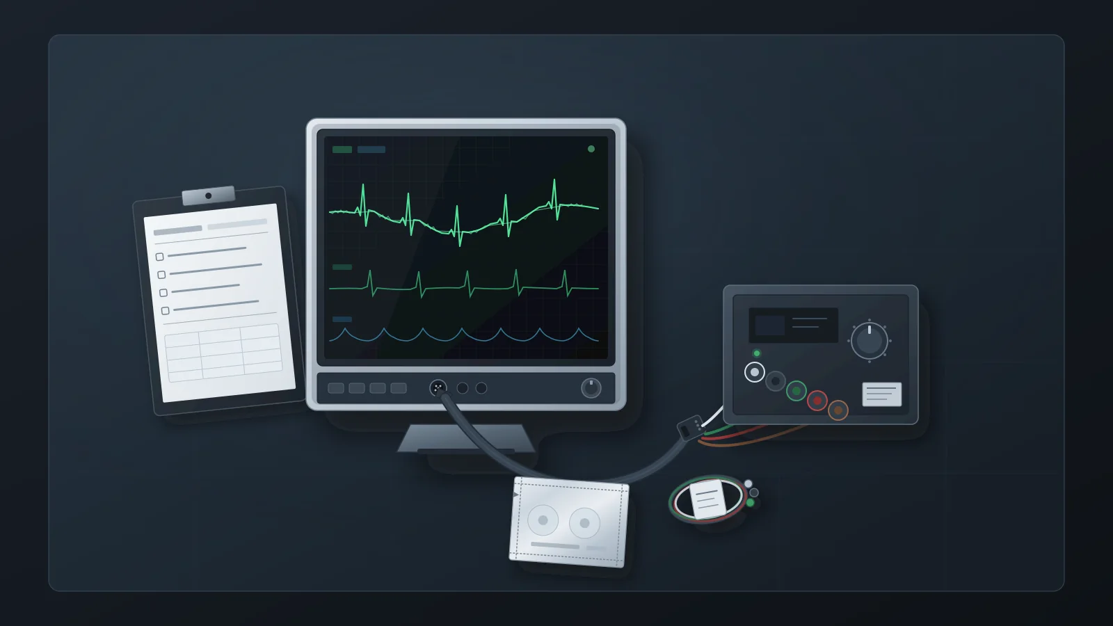
Nursing reports a fuzzy ECG trace, a wandering baseline and intermittent false arrhythmia alarms, and asks biomed whether the monitor is failing. The reflex response—pull the monitor, bench-test it with shop cables, return it as “no fault found”—can leave the real cause at the bedside. A Philips application note on ECG quality describes the electrode-skin interface as a frequently overlooked major source of artifact, and the leads, cables and equipment around the patient can generate artifact too.
This article treats the complaint as a signal-chain isolation task and sets out what HTM should observe, reproduce, substitute and record at each step. It does not replace the monitor manufacturer's service literature: acceptance limits, test procedures and filter behavior vary by model and must come from that documentation. And it stops where clinical judgment starts—deciding whether a rhythm is real is not an HTM call.
What Counts as an ECG Artifact on a Monitored Patient
An artifact is anything on the ECG that is not caused by the electrical activity of the heart. Philips lists the common sources as electrical interference, muscle tremor, patient movement and loss of electrode contact. A 2018 review in the Annals of Noninvasive Electrocardiology adds tremor of many origins, chest compressions during CPR, alternating-current interference, poor grounding, devices operating nearby, and electrode misplacement or interchange. For a service team, the useful grouping is by where the signal is most likely being corrupted:
Baseline wander: a slow, undulating baseline that often tracks respiration or movement. Electrode contact and skin preparation are the first things to check, well before the monitor's amplifier.
Muscle and movement artifact: irregular fine fuzz from skeletal-muscle activity such as shivering, tension or tremor. The cause is in the patient, so a bench test can only show how the monitor handles a synthetic version.
Mains interference: a regular thickening of the baseline at the local line frequency, 50 or 60 Hz. The review links it to nearby equipment, poor grounding, and absent or poorly functioning AC filtering.
Contact loss and lead-off: abrupt steps, dropouts or lead-off indications from dried gel, lifting electrodes or loose connections. Philips also names defective ECG cables or lead wires as a cause of poor contact.
Accessory-generated patterns: spikes, bursts or regular patterns that change when a lead set, trunk cable or nearby device is changed. These are the cases where ordered substitution matters most.
These classes explain why the complaint so often lands with biomed. Staff see the problem on the monitor's screen and reasonably log it as a monitor fault. MedTen—a vendor that sells compatible cables and lead wires, so its guide is not a neutral authority—describes the pattern plainly: biomed investigates the monitor, the monitor passes bench testing, and the accessory or environmental cause is found only after repeated calls. Its suggested inspection order runs skin, electrode, lead wire, trunk cable, then monitor. HTM does not need to accept the vendor's claim that most artifact originates before the monitor to see the value of that order: each step is cheaper and less disruptive than the next, and each produces a result that can be written down.
The Central Question: Is the Artifact Reproducible at the Bench?
The pivotal fork is whether the artifact can be reproduced with a controlled input. Bring the monitor or acquisition module to the bench together with the trunk cable and lead set that were in use at the bedside, tagged so they stay identifiable. Testing only with shop cables tests a different signal path from the one that produced the complaint.
A Fluke Biomedical white paper on testing multi-function monitors describes the bench convention. Testing the ECG channel “should include a variety of normal waveforms, with and without added artifacts,” with the monitor connected through its normally supplied ECG cable and the color coding matched to the simulator's AAMI/IEC connectors. Adding 50 Hz or 60 Hz artifact “will confirm the effectiveness of the filter for those power-line frequencies.” The paper also advises technicians to settle on a list of ECG-channel tests appropriate to each model and apply it consistently, so an artifact workup should reuse the department's standard ECG test list rather than an improvised one.
Start with a clean normal-sinus input at the simulator's default settings. If the bedside artifact appears on this clean input, the problem sits somewhere in the path under test—lead set, trunk cable, module or monitor—and substitution can narrow it down. If the trace is clean, add the simulator's artifact modes one at a time and confirm that the monitor renders them and that its line filter behaves as the operator and service manuals describe.
As one device-specific example, the Fluke PS410 ECG simulator manual (a historical Rev. 1 document from December 2007) lists five superimposed artifact modes—50 Hz, 60 Hz, muscle, baseline wander and respiration—whose stated purpose is “to evaluate the effect of these artifacts on ECG accuracy.” The same manual lists non-clinical performance waveforms. Other simulators differ, and none of these values is an acceptance criterion:
square waves at 0.125 Hz and 2 Hz;
a 2 Hz triangle wave;
pulses at 30, 60 and 120 BPM with a 60 ms width;
sine waves at 0.5, 5, 10, 40, 50 and 60 Hz, fixed at 1 mV.
The Fluke white paper describes what non-clinical waveforms are for in general terms: checking the monitor's frequency response, gain, ability to detect specific elements of the ECG, and recorder performance. What counts as a pass for each one comes from the monitor's service literature, not from the simulator.
Be explicit about what the bench result proves. A clean bench trace shows that the monitor path rendered the simulator's signals correctly under bench conditions. It does not prove the monitor is fault-free under every bedside condition, and it says nothing about the patient: simulator artifact modes are synthetic approximations and cannot reproduce every clinical artifact. The same limit applies to other parameters, as discussed in what a passing pulse oximeter simulator test does not prove.
The standard itself bounds what a quiet trace means. According to MEDTEQ's review of the 2011 edition of IEC 60601-2-27, the input-noise test now requires ten 10-second runs with at least nine passing, and the edition added low-amplitude heart-rate tests. Those are design-verification tests with defined test networks. A few minutes of quiet trace on a service bench is not the same test and should not be recorded as equivalent to it.
The Observation Matrix: Stimulus, Leads and Accessories, Filters, Environment
The matrix below is the working tool for an artifact ticket. Each row starts from something the reporter or technician can see, names the layer it most often implicates, states what the bench can and cannot show, and lists what to record. Numeric acceptance limits are deliberately absent: they belong to the monitor's service literature.
| Observation | Layer it usually implicates | What the bench can show | What to record | Escalation boundary |
|---|---|---|---|---|
| Regular mains-rate thickening of the baseline (50 or 60 Hz) | Line-frequency coupling from nearby equipment or wiring; filter setting; grounding | Injected 50/60 Hz artifact checks the line filter; the room's interference cannot be reproduced | Displayed filter setting at intake; nearby powered equipment; cable routing; bench result with line artifact | Refer recurring interference in one location to facilities or electrical-safety review; leave filter defaults to clinical and manufacturer guidance |
| Slow baseline wander that tracks breathing or movement | Electrode contact, skin preparation, patient respiration or movement | Baseline-wander or respiration modes show how the monitor renders drift; the patient cause stays at the bedside | Electrode brand and type, expiry and pack condition; displayed filter mode; whether wander persists with fresh electrodes | Skin preparation and electrode practice go to the clinical team; a filter-mode change is a clinical configuration decision |
| Irregular fine fuzz | Muscle tremor, shivering or movement; less often a damaged lead | The muscle-artifact mode shows only the monitor's handling of synthetic tremor | Displayed lead; lead-set age and condition; whether the pattern changes after a lead-set swap | Patient-origin tremor is a clinical matter; Philips advises improving patient comfort rather than adjusting a filter |
| Fixed or repeating pattern in every lead that does not fit the patient | Lead set, trunk cable, or a co-located device or its leads | A clean simulator input through the same cable and leads shows whether the pattern travels with the accessories | Order of each swap and the result; identities of co-located devices and their leads | Remove the implicated accessory from service and retain it until the record is closed |
| Lead-off indication or dropout on one lead | Electrode contact, a single lead wire or a connector | A known-good lead set on the simulator separates the accessory from the input channel | Which lead; lead-off status as displayed; result with the known-good lead set | If the fault persists on the simulator with known-good accessories, escalate the module or monitor |
| Noise on all channels that persists with known-good accessories | Acquisition module or monitor front end | Persistence with a clean input and known-good cable and leads is the key reproduction | Simulator identity and calibration due date; accessories used; test list applied; strips or screenshots where available | Escalate with the evidence to the OEM or an authorized service provider; no internal rework |
| Bedside artifact that clears on the bench with the same cable and leads | Environment, electrode practice or patient-specific factors | Nothing further: the bench has cleared the monitor path under test | Location, nearby equipment, cable routing, electrode practice observed, time pattern of the complaint | Facilities or clinical follow-up; reopen the ticket if the same asset draws the complaint again |
Two cautions apply to every row. First, never unplug, power down or move equipment in clinical use on a patient to test an interference hypothesis; note the equipment and arrange any test with the clinical team or with the room empty. Second, the matrix is a recording tool, not a repair procedure: any work inside the monitor follows the manufacturer's service documentation and your program's authorization rules.
When the Accessory Is the Fault: Evidence and Limits
A 2021 case report by Imhoff and Casey in Clinical Practice and Cases in Emergency Medicine shows why substitution order matters. An ECG recorded in an emergency department showed a fixed-frequency square-wave artifact in all leads. The patient was wearing an event monitor, so the nurse first turned it off and removed it, then replaced the ECG machine's main cable; the repeat ECG was unchanged. Exchanging the room's cardiac monitor leads resolved the artifact completely. The original monitor leads showed no visible damage.
Two lessons carry over to HTM work. Visual inspection does not clear a lead set; substitution with a known-good set does. And the faulty accessory was not part of the recording device at all—it belonged to the bedside cardiac monitor in the same room—so isolation has to include co-located equipment and its leads. The limits matter as much: this is a single case report, not a prevalence estimate, and it does not show that monitors are usually blameless. The authors' own conclusion is narrower—keep a low threshold for suspecting artifact when the ECG does not fit the patient, and isolate the source step by step.
The electrode-skin interface is the other recurring accessory layer. The Philips note cites a study in which abrasion with fine sandpaper material helped reduce average skin impedance from 354 kΩ to 20 kΩ. Skin preparation is clinical practice, but several electrode facts in the same note can be checked and recorded by HTM during a workup:
only electrodes specified by the monitor or defibrillator manufacturer are in use;
all electrodes on the patient are the same brand and type, which Philips recommends to help minimize noise;
the use-by date is respected, and bulk packs are used promptly or tightly resealed, because air exposure dries electrodes and reduces their adhesive and conductive properties—Philips suggests writing the opening date on the pack;
electrodes are changed periodically during long-term monitoring, following the manufacturer's specifications.
Philips also attributes poor electrode contact to poor skin preparation, dried gel, or defective ECG cables or lead wires, which is why electrode and lead-set findings belong in the same record. MedTen adds a compatibility point that is easy to miss after a purchasing change: cables and lead wires are model-specific, and compatibility must be verified at the monitor-model level, not just the brand. When artifact follows an accessory change, record the part numbers on both sides of the change.
Substitute one element at a time and record the result after each: fresh electrodes from a newly opened, in-date pack; then a known-good lead set; then a known-good trunk cable. Only when the artifact persists with known-good accessories, and the bench reproduces it with a clean input, does the monitor or module become the working hypothesis. Changing several components at once can clear the complaint while hiding which one caused it, and can return a defective accessory to circulation.
Filter, Lead, Gain, and Sweep: Recordable Display Facts
A note that says “trace noisy” is not evidence; the display settings at the time of the complaint are. MEDTEQ's review of the 2011 edition of IEC 60601-2-27 lists a display-indication requirement covering filter settings, selected leads, the gain indicator and sweep speed. MEDTEQ describes its table as based on a document review only, so confirm clause wording against the purchased standard before quoting it. The practical point still holds: these four settings are meant to be visible on a compliant monitor, so they can be recorded.
IEC 60601-2-27 is the particular standard for basic safety and essential performance of ECG monitoring equipment. The IEC catalog scopes it to hospital use, including use in ambulances and air transport, and places home-use monitors, Holter monitors, fetal heart rate monitoring and pulse plethysmographic devices outside it. FDA lists Edition 3.0 (2011, including Corrigendum 1 of 2012) as recognized consensus standard 3-126, entered on 18 December 2023, with partial recognition: one subclause exempting patient cables from an EMC requirement is not recognized. Recognition concerns premarket submissions and does not set HTM service duties, which is why this article uses the standard only to identify what a compliant display should show.
At intake, before touching any setting, transcribe:
Filter setting: the mode or bandwidth label exactly as displayed. Filter names and bandwidths differ by manufacturer, so record the label and look up its meaning in the operator's manual rather than translating it.
Selected leads: which lead each displayed waveform shows, and which lead feeds arrhythmia analysis if the monitor indicates it.
Gain indicator: the displayed gain or scale for each ECG waveform.
Sweep speed: the displayed sweep speed.
Lead-off and signal-quality indications: whatever the monitor shows, recorded as displayed.
If a setting is changed during the workup, record the change and restore the clinical configuration, or hand the decision to the clinical owner. Filter and lead selection on a monitor in patient use are clinical configuration decisions, not service adjustments.
Gain causes similar confusion. Philips notes that in many monitors increasing the displayed gain does not change the signal the monitor analyzes. Its lead-selection guidance recommends a lead whose QRS amplitude exceeds 0.5 mV and cites a minimum QRS detection level of 0.15 mV under AAMI EC13; a signal that is too weak can produce false asystole alarms. Lead selection is a clinical choice, but HTM can record the displayed lead and gain and flag a small QRS on the analyzed lead so the clinical team can decide.
The Clinical Boundary: HTM Evidence, Not Rhythm Interpretation
Whether a given tracing is artifact or a real arrhythmia is a clinical judgment. The American Heart Association's 2017 update to its practice standards for ECG monitoring in hospital settings addresses alarm management, staff education and documentation in the electronic health record as parts of the clinical monitoring program. It is not an HTM bench protocol and should not be cited as one, but it places alarm management and monitoring documentation within the clinical program rather than the service bench.
In practice, HTM records what the equipment did and what changed it, and leaves the clinical meaning to clinicians. Compare two ways of closing the same ticket:
Technical record: “Monitor bench-tested with a simulator in calibration through the bedside lead set and trunk cable. Clean normal-sinus input displayed without the reported artifact on all displayed leads. Bedside artifact cleared after the lead set was replaced; original lead set tagged and removed from service. Filter and lead settings recorded as found and not changed.”
Clinical conclusion to avoid: “Confirmed the VT alarm was false and the rhythm was only muscle artifact.”
The first states observations and substitutions that anyone can verify. The second adjudicates a rhythm, which cannot be done from the service bench. When false arrhythmia alarms recur on a unit, HTM's contribution is the technical evidence—equipment integrity, accessory identities and condition, settings as found, and any unresolved environmental factors—handed to the unit's clinical leadership for disposition. Alarm-function checks after service are a separate task, covered in patient monitor alarm verification after service.
What the Work Order Should Show
For U.S. hospitals, the documentation duty comes from the Medicare Conditions of Participation. Under 42 CFR 482.41(d)(2), facilities, supplies and equipment must be maintained to ensure an acceptable level of safety and quality. CMS survey letter S&C 14-07 (December 2013), which interprets that requirement and cites it under its earlier designation, 482.41(c), states that all equipment must be inspected and tested for performance and safety before initial use and after major repairs or upgrades, and expects hospitals to document their maintenance activities. Confirm that no later CMS guidance has superseded the letter for your setting. General record contents are covered in medical equipment service records; for an artifact ticket, the record should show:
Complaint and context: unit, asset ID, the artifact as reported and as observed, which leads, and whether it was continuous, intermittent or linked to movement.
Display settings as found: filter, selected leads, gain, sweep speed, and lead-off or signal-quality indications.
Accessories in use: identities (part number, and lot or serial number where available) and condition of the electrodes, lead set and trunk cable, plus co-located devices and their leads.
Substitutions in order: each element changed, and whether the artifact persisted or cleared after each change.
Bench evidence: simulator identity and calibration due date, the ECG test list applied, the artifact modes used, and the result.
Environment: nearby powered equipment, cable routing, and any pattern by location or time of day.
Disposition: accessory removed and retained, clinical handoff, facilities referral, or escalation to qualified service—plus anything left unresolved.
Post-work verification: where the corrective work counts as a major repair under your program, the performance and safety testing required before return to service; see major repair return-to-service testing and electrical safety testing after repair.
An accessory-only fix, such as replacing a lead set, may fall outside your program's definition of a major repair. Record the decision either way so a reviewer or surveyor can follow it.
When to Escalate to Qualified Service
Escalate the monitor or module when the evidence points inside it:
the artifact persists on the bench with a clean simulator input through a known-good lead set and trunk cable, using a simulator that is in calibration;
the monitor fails a performance check in its own service literature, or a display or lead-off indication does not behave as the service manual describes;
the same asset keeps generating artifact tickets that clear temporarily after accessory changes and then return.
Escalation means handing over evidence. Tag the device out of service under your program's procedure, attach the work-order record and any recorder strips or screenshots, and send it to the OEM or an authorized service provider, with the accessories used in testing if they are requested. When it returns, it needs whatever return-to-service verification your program requires for major repairs.
The aim is for every artifact ticket to end with a supported action—an accessory, environment, clinical-practice or escalation step—and a record that shows how it was reached. When the evidence does point to the monitor, that same record lets qualified service start from facts rather than from a complaint.