
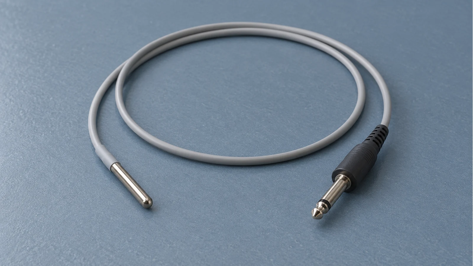
The Opening Case: A Passed PM and a Wrong Reading
Consider a hypothetical service call: a monitor passed its scheduled temperature simulation at 37.0 °C, but a week later its patient reading differs from another thermometer. The earlier pass and the later complaint can both be valid observations. The simulator replaced the physical probe; it did not establish the performance of the probe subsequently used on the patient. Nor does a difference between two clinical measurements, by itself, identify which device is wrong.
For the connection illustrated in the ProSim 8/8P manual, electrical temperature simulation enters at the monitor temperature input. It exercises the connected monitor path at the chosen settings. The detached probe, its cable, and accessories omitted from that setup receive no verification. If an actual extension or adapter is included between tester and monitor, record it as part of the connected path rather than automatically calling it excluded. Source: ProSim 8 / ProSim 8P Users Manual.
This guide concerns analog thermistor temperature paths, including compatible YSI-series inputs. Proprietary digital probes, probe-identification systems, and other sensing technologies need their own documentation. Its bench checks are verification decisions, not instructions to adjust a probe or modify a monitor.
What a Temperature Simulation Actually Tests
Fluke describes the ProSim 8/8P as a basic-operation tester for patient monitors, used by trained biomedical equipment technicians. Its cable determines whether the temperature output simulates YSI Series 400 or 700. A compatible connector alone therefore does not establish the correct simulated probe characteristic. Check the tester cable, monitor input specification, and selected mode together. Source: ProSim 8 / ProSim 8P Users Manual.
| ProSim 8/8P mode | Published output specification | Service implication |
|---|---|---|
| Standard temperature | 30.0–42.0 °C in 0.5 °C steps; accuracy ±0.4 °C | Use only where the device procedure and required test capability permit. |
| High accuracy temperature | Fixed 0, 24, 25, 37, and 40 °C; accuracy ±0.1 °C | Confirm availability on the actual tester; pre-2025 units may lack this mode. |
These are tester output specifications, not monitor pass/fail limits or a complete measurement-uncertainty budget. Use the monitor service procedure to establish required points and acceptance criteria. A numerical match at one point does not establish the entire range, and a temperature display check does not establish alarm behavior unless the applicable alarms were exercised. The published tester accuracy must be adequate for the intended decision.
The Chain the Simulation Never Touches
The measurement starts at the patient site, passes through the physical sensor and its cable, then through any extension or adapter to the monitor input, processing, display, and alarms. Map the actual assembly before testing: the same monitor may be used with different accessories, and a bench setup may omit the component involved in the complaint.
flowchart TD
  SITE["Patient measurement site"] --> SENSOR["Physical thermistor probe"]
  SENSOR --> CABLE["Probe cable and connector"]
  CABLE --> ACCESSORY["Extension or adapter if used"]
  ACCESSORY --> INPUT["Monitor temperature input connector"]
  INPUT --> PROCESS["Monitor processing and display"]
  PROCESS --> ALARM["Alarms only verified when exercised"]
  SIM["Compatible electrical simulator replaces probe"] -.-> INPUT
  THERMAL["Documented thermal comparison includes physical probe"] -.-> SENSOR
CONTEXT["Clinical assessment of site and application"] -.-> SITEYSI component documentation illustrates why temperature matters to an electrical check: order code 44004 has a nominal resistance of 2,252 Ω at 25 °C. The catalog describes interchangeability as tracking a specified resistance curve over a stated range, with tolerance depending on the component. It also directs readers to separate resistance-versus-temperature tables. A component specification does not establish the acceptance criteria or permitted immersion conditions for a finished medical probe. Source: YSI Precision Thermistors and Probes (44000/46000 series specifications).
Use the exact probe specification to identify the curve, compatible monitor inputs, and approved accessories. Do not identify an unknown probe solely from an approximate resistance or plug shape. An adapter must be documented as compatible with both ends; do not assume that physical fit changes one probe characteristic into another.
The clinical measurement site is another boundary. Hymczak and colleagues describe how both measurement system and anatomical site affect temperature results; skin measurements do not reliably represent core temperature. A skin-versus-esophageal difference is therefore not a ready-made calibration error, and there is no fixed site correction suitable for every patient. Give the clinical team the equipment findings while it evaluates site, placement, timing, and patient conditions. Source: Core Temperature Measurement - Principles of Correct Measurement, Problems, and Complications.
Instrument-Only Versus Combined Checks: What OEM Documents Do
The SureTemp Plus 690/692 service manual makes the distinction explicit. Its Cal-Key check removes the probe and expects 36.3 ±0.1 °C. Separate procedures include the unit and probe: the Model 9600 tester uses two settings, whereas the 9600 Plus procedure uses 36.0, 38.5, and 41.0 °C. The manual also describes Monitor mode for a combined check against a known temperature, including a circulating bath. These procedures and their limits belong to these thermometer models; they are not bedside-monitor criteria. Source: SureTemp Plus Model 690 and 692 Thermometers, Service Manual.
The 3M Model 370 temperature-monitoring control unit provides another layered example. Its manual separates verification-stick display checks from monitor-output checks and specifies a multimeter capability for the latter. The monitor-output procedure measures at the patient-monitor connector cable contacts, so the specified cable path matters. This is a temperature-monitoring system with a monitor interface; its heated sensor technology should not be treated as an ordinary passive thermistor probe. Source: Temperature Monitoring Control Unit Model 370 Operator's Manual.
| Model 370 reference | Display output in Table 6-1 | Monitor-output resistance in Table 6-3 |
|---|---|---|
| 31 °C | 31.0 ±0.1 °C | 1,739 ±15 Ω |
| 36 °C | 36.0 ±0.1 °C | 1,412 ±12 Ω |
| 41 °C | 41.0 ±0.1 °C | 1,152 ±10 Ω |
Those are Model 370 values, not a universal YSI table. The manual permits institutional requirements to determine whether additional reference temperatures are needed and calls for discontinuing use when verification is outside limits. For a control-unit/patient-monitor discrepancy beyond ±0.2 °C, its troubleshooting path includes securing or replacing the monitor cable, checking output, and contacting technical support.
The coverage matrix below is a synthesis of the cited test boundaries. Read the method beside its exclusions before deciding what remains to be verified.
| Verification method | Path included | Path excluded | Meaning of a pass |
|---|---|---|---|
| Electrical simulation at monitor input | Connected simulator cable and monitor input-to-display path; alarms if exercised | Replaced physical probe, its detached cable and accessories, patient site | Response at the required test points and conditions; add any actual extension included in the setup to the record. |
| SureTemp Plus Cal-Key | Thermometer instrument with fixed-value key | Removed clinical probe and its thermal response | Instrument-only result under that model’s specified procedure. |
| SureTemp Plus combined thermal check | The specified thermometer and physical probe pairing | Patient physiology and any accessory omitted from the setup | Combined response under the documented tester or bath conditions. |
| Model 370 verification sticks and output measurement | Sensor cable, control-unit display, and connected monitor-output cable path as documented | Replaced patient sensor and the bedside monitor’s own input electronics | Separate display and output results within that model’s limits. |
| Documented probe resistance check | Isolated passive probe and the conductors actually connected | Monitor electronics and patient application site | A screen, or response at known temperatures when the specified curve and method support that assessment. |
| Approved combined probe/monitor thermal comparison | Physical probe, included clinical accessories, monitor processing and display | Patient site, perfusion, and any untested functions | Evidence for the assembly and conditions tested, without reproducing clinical physiology. |
Verifying the Probe Itself: Resistance at Known Temperature
Choose the method from the documentation for the actual assembly. A component catalog explains the resistance-temperature principle, but it cannot authorize a universal test for every clinical probe. If the necessary probe instructions, curve, or acceptance limits are unavailable, hold the suspect assembly for qualified assessment. Do not fill a documentation gap with an internet tolerance.
Identify and inspect: record the probe and accessory part numbers, intended monitor input, cleaning status, and visible damage. Remove a suspect assembly from clinical circulation under the facility process while the complaint is investigated.
Check the permitted electrical screen: for an isolated passive probe, use only a documented resistance or continuity method with suitable test equipment. An open, short, or unstable indication supports further fault investigation; a plausible reading at an unknown temperature is not an accuracy pass. Do not connect an ohmmeter to an assembly in patient use.
Verify temperature response when authorized: compare resistance at known, stable temperatures against the exact curve and tolerance, or use an approved combined probe-and-instrument thermal comparison. Select points, stabilization conditions, reference capability, and handling from the applicable procedure rather than from a generic list.
Preserve the clinical configuration: identify whether the real extension and adapter were included. If accessories are evaluated separately, link those results to the combined assembly. Record unresolved components instead of silently extending the test conclusion to them.
An unmeasured workshop temperature is not a reference point: a temperature-dependent resistor can have different legitimate readings at different room temperatures. Even a documented single point establishes only the response at that condition. Range verification needs the points and method required by the product procedure; it cannot be inferred from a nominal 25 °C component value.
Which Accuracy Number You Are Holding It To
FDA recognition entry 3-203 lists IEC 80601-2-49:2018 with Amendment 1:2024 for multifunction patient monitors, with partial recognition entered on December 22, 2025. Its published scope excludes requirements for individual physiological monitoring units and explains that related particular standards address those units. The recognition record does not supply a temperature-channel service tolerance. Source: FDA Recognized Consensus Standards entry: IEC 80601-2-49 Ed 1.1 (2024-09) Multifunction patient monitors.
FDA entry 6-421 describes ISO 80601-2-56 as applying to electrical clinical thermometers with their accessories, including equipment that measures body temperature. It is not limited simply to standalone thermometer housings. The entry lists continuous-measurement and clinical electronic thermometer product codes, but does not reproduce numerical laboratory-accuracy clauses. Do not use it to invent a service limit or assert that a monitor temperature function is categorically outside its scope. Source: FDA Recognized Consensus Standards entry: ISO 80601-2-56 Ed 2 (2017, incl. AMD1:2018) Clinical thermometers for body temperature measurement.
| Decision | Acceptance source | What cannot substitute |
|---|---|---|
| Does the monitor channel pass? | Applicable monitor/module service procedure and documented test capability | The simulator accuracy specification alone |
| Does this physical probe pass? | Exact finished-probe specification and authorized verification method | A component tolerance or nominal room-temperature resistance alone |
| Does the combined assembly pass? | Applicable system procedure, including compatible accessories | Separate passes that omitted the clinical accessory path |
| What standard applies? | Device documentation and the relevant standard scope and requirements | An FDA recognition listing treated as a universal servicing rule |
Record the source and revision of the limits before comparing results. If the procedure requires a capability the available tester cannot provide, obtain the correct test capability or escalate the assessment. Passing a less demanding check does not close the original requirement.
Fault-Isolation Map: Probe, Cable, Channel, or Context
Use the following map to select the next documented check. These are investigation branches, not diagnoses from symptoms. Start by arranging safe clinical monitoring with the care team; bench work on a suspect assembly must not interrupt patient monitoring without an agreed alternative.
| Observation | Next evidence to collect | Decision boundary |
|---|---|---|
| Simulation passes but the clinical complaint remains | Confirm probe identity, accessories, and the simulator connection point; obtain the documented physical-probe or combined check | Keep the complaint open until the omitted path and clinical context are assessed. |
| Open, intermittent, or erratic readings | Document the actual message and configuration; use approved inspection and isolation checks for the probe, cable, and input | Do not infer a universal fault code or prescribe a cable bend angle. |
| Persistent offset | Check compatible parts, reference conditions, tester mode, and the included accessory path | An offset alone does not establish thermistor drift or an internal circuit failure. |
| Suspected wrong-series probe or adapter | Compare exact part numbers with the monitor and accessory compatibility documentation | Quarantine an unresolved combination; do not release it based on physical fit. |
| Monitor fails the prescribed simulation | Confirm tester capability and setup, then follow the model service escalation process | Keep the monitor out of clinical use pending the required corrective work and verification. |
| Model 370 control unit and monitor disagree | Use that model’s cable and output troubleshooting instructions | Its ±0.2 °C discrepancy criterion remains model-specific. |
| Measurements differ across anatomical sites | Document site, timing, and application; give verified equipment findings to the clinical team | Site effects neither prove a probe fault nor automatically clear the equipment. |
A replacement accessory that resolves the symptom is useful isolation evidence, but release still requires the applicable checks of the final configuration. Do not prescribe probe splicing, connector solvents, receptacle replacement, or internal electronic adjustments from a generic symptom table. Work beyond documented checks belongs with appropriately qualified service personnel.
Records, Test Tools, and the Return-to-Service Line
42 CFR 482.41(d)(2) requires hospital facilities, supplies, and equipment to be maintained for acceptable safety and quality. CMS S&C 14-07-Hospital, dated December 20, 2013, explains inspection and performance/safety testing before initial use and after major repairs or upgrades. Its maintenance framework permits documented, risk-based AEM changes to activities or frequencies where eligible, with specified exclusions; it is not blanket permission to omit a probe assessment. Source: 42 CFR 482.41 - Condition of participation: Physical environment; S&C: 14-07-Hospital: Hospital Equipment Maintenance Requirements.
The CMS letter also calls for maintained, reliable maintenance tools capable of results equivalent to those the equipment manufacturer requires. It does not expressly mandate NIST traceability for every tool or name a categorical ban on homemade resistor boxes. For release decisions, use equipment with documented suitability and calibration status under the applicable procedure. An uncharacterized resistor box supplies no adequate basis for a quantitative acceptance claim.
A useful temperature-service record should capture the following. These are practical record recommendations, rather than a claim that the cited regulation mandates this exact form:
Identity and complaint: monitor/module identity, physical probe and accessory identifiers, reported behavior, and the clinical configuration relevant to the investigation.
Procedure and limits: document title/revision, specified settings and acceptance criteria, plus any approved facility procedure governing the work.
Test boundary: connection point, whether the physical probe was replaced or thermally exercised, and the actual extensions or adapters included and excluded.
Test capability and results: tester/model, cable and mode, calibration status, reference conditions where relevant, numerical observations at each required point, and alarm results recorded separately.
Disposition: failed or unresolved items, corrective work or replacement identity, final configuration checks, responsible personnel, and the basis for release or continued hold.
For a simulator-only check, a clear scope statement is: “Temperature response checked by electrical simulation at the monitor input using the documented cable and mode. The detached physical probe and its clinical accessories were excluded. Results apply to the settings tested; alarm results are recorded separately.” Change that statement if an actual extension was included, and attach the physical-probe or combined-test evidence when performed.
For related records guidance, see medical equipment calibration certificates and return-to-service testing after major repairs. A simulator pass is one bounded result. Release depends on completing the checks required for the actual assembly and resolving the complaint within the documented service process.